Eureka AIR delivers breakthrough ideas for toughest innovation challenges, trusted by R&D personnel around the world.

Level shift driving power detection radio frequency module for smart home

A level shifting, smart home technology, applied in electrical components, transmission monitoring, transmission systems, etc., can solve problems such as misoperation of radio frequency equipment, increased pressure on processing chips, and radio frequency modules without power detection power, etc., to increase work life, prevention of misoperation, avoidance of temperature drift and effects of various disturbances

Inactive Publication Date: 2015-10-28
CHENGDU HONGYI TIANCHENG TECH
View PDF5 Cites 3 Cited by
  • Summary
  • Abstract
  • Description
  • Claims
  • Application Information

AI Technical Summary

Problems solved by technology

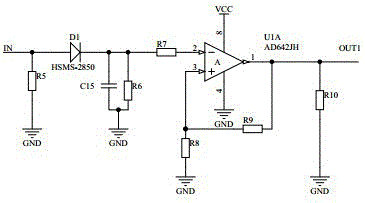
However, the general RF module does not have a power detection power, which cannot let the user know the current working status of the device. When working for a long time or receiving other signals with abnormal power, the amplifier and other auxiliary equipment in the module are easy to overload and reduce the power consumption. The working life of the radio frequency module is shortened, and it is easy to cause misoperation of the radio frequency equipment. At the same time, the output of the power detection circuit is a near-linear voltage signal instead of a logic high and low level signal, which is easily disturbed and is not suitable for directly controlling the working status of the radio frequency module. Extract the voltmeter from the memory of the processing chip to judge the working status, which increases the pressure on the processing chip

Method used


Image

  • Level shift driving power detection radio frequency module for smart home
  • Level shift driving power detection radio frequency module for smart home
  • Level shift driving power detection radio frequency module for smart home

Examples


Embodiment Construction

[0017] Below in conjunction with accompanying drawing, the present invention is described in detail.

[0018] In order to make the object, technical solution and advantages of the present invention clearer, the present invention will be further described in detail below in conjunction with the accompanying drawings and embodiments. It should be understood that the specific embodiments described here are only used to explain the present invention, not to limit the present invention.

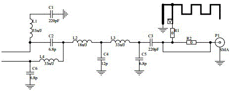
[0019] As an embodiment of the present invention, the antenna matching circuit considers receiving a signal with a frequency of 433M, the integrated antenna is connected to the load resistor R1, the SMA interface is connected to the load resistor R2, and the other end of the resistor R1 and R2 is connected to a 200pF capacitor C3, and the capacitor C3 The other end is connected to a 33nH inductor L3 and grounded through a 12pF capacitor C4. Both ends of L3 are connected to C3 and an 18nH inductor ...


PUM


Abstract

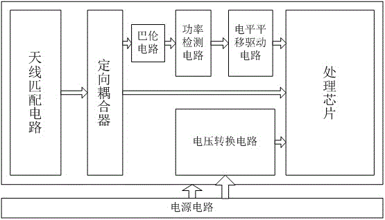
The invention discloses to a level shift driving power detection radio frequency module for a smart home, relating to the field of radio frequency modules and solving a problem of working control of the radio frequency module. The interference current and the temperature drift can be effectively avoided through a level shift driving differential control signal, and a control effect is accurate. The level shift driving power detection radio frequency module comprises an antenna matching circuit, a directional coupler, a balun circuit, a power detection circuit, a power circuit, a voltage conversion circuit, a processing chip and a level shift driving circuit, wherein a signal of the antenna matching circuit is divided into two ways through the directional coupler, one way is converted to a one-way signal to a power detection signal circuit through the balun circuit, a detection signal is transmitted to the processing chip, and the working condition of the radio frequency module is determined according to a voltage worksheet in a storage of the processing chip to enable a user to know the current working condition of equipment, so that an amplifier and other accessory equipment in the module can be prevented from overloading, the service life of the radio frequency module is prolonged, and the faulty operation to radio frequency equipment is prevented.

Description

technical field [0001] The invention relates to the field of radio frequency modules, in particular to a level shift driven power detection radio frequency module for smart home use. Background technique [0002] RF modules are widely used in the field of Internet of Things, especially in the field of smart home equipment. RF modules are heavily used in devices such as wireless switches and wireless motorized shades and projector controls. However, the general RF module does not have a power detection power, which cannot let the user know the current working status of the device. When working for a long time or receiving other signals with abnormal power, the amplifier and other auxiliary equipment in the module are easy to overload and reduce the power consumption. The working life of the radio frequency module is shortened, and it is easy to cause misoperation of the radio frequency equipment. At the same time, the output of the power detection circuit is a near-linear vo...

Claims


Application Information

Patent Timeline
Patent Type & Authority Applications(China)
IPC IPC(8): H04B17/00H04B1/40
Inventor 严立
Owner CHENGDU HONGYI TIANCHENG TECH
Why Eureka
Eureka Blog
Learn More