
Exhaust purification device

A technology of exhaust purification device and exhaust device, which is applied in the direction of exhaust device, noise reduction device, catalyst carrier, etc., can solve the problems of different lengths and complex structures, and achieve the effects of simple structure, improved purification performance and simple structure

Active Publication Date: 2015-10-21
HONDA MOTOR CO LTD
View PDF10 Cites 5 Cited by
  • Summary
  • Abstract
  • Description
  • Claims
  • Application Information

AI Technical Summary

Problems solved by technology

However, in the above exhaust purification device, the first catalyst carrier on the upstream side and the second catalyst carrier on the downstream side have different outer diameters, and the second catalyst carrier and the third catalyst carrier have the same outer diameter but different lengths. Three types of catalyst supports need to be prepared, and the structure becomes complicated

Method used


Image

  • Exhaust purification device
  • Exhaust purification device
  • Exhaust purification device

Examples


no. 1 Embodiment approach

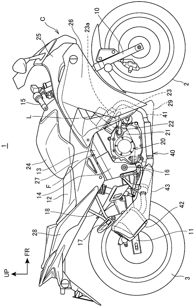
[0048] figure 1 It is a right side view of the motorcycle of the first embodiment of the present invention.

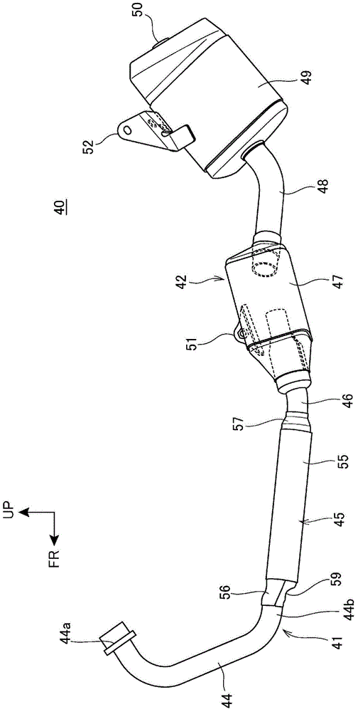
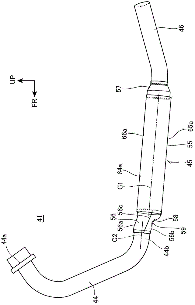
[0049] The two-wheeled motorcycle 1 is a straddle-type vehicle, and an engine 20 is arranged in the center of the front and rear of the body frame F. The front fork 10 supporting the front wheel 2 is supported on the front end of the body frame F in a steerable manner, and the rear wheel 3 is supported by the front fork 10. A swing arm 11 is provided on the rear side of the body frame F, and a seat 12 on which an occupant sits is provided above the body frame F. As shown in FIG. Most of the body frame F is covered with a body cover C made of resin.

[0050] The body frame F has: a head pipe (not shown) provided at the front end; a pair of left and right main frames 13 extending obliquely downward from the head pipe to the rear; To the central vehicle frame 14; From the top of the central vehicle frame 14 to the left and right pair of seat frames (not shown) extending...

no. 2 Embodiment approach

[0115] Below, refer to Figure 5 ~ Figure 7 A second embodiment to which the present invention is applied will be described. In this second embodiment, the same reference numerals are assigned to the same components as those in the above-mentioned first embodiment, and description thereof will be omitted.

[0116] In the above-mentioned first embodiment, the case where the catalyst storage pipe 45 is arranged below the engine 20 has been described. The implementation is different.

[0117] Figure 5 It is a right side view of the motorcycle 101 of the second embodiment.

[0118] The two-wheeled motorcycle 101 is a straddle type vehicle, and an engine 120 is arranged in the center of the front and back of the body frame 108. The front fork 110 supporting the front wheel 102 is supported on the front end of the body frame 108 in a steerable manner, and the rear wheel 103 is supported. The swing arm 111 is provided on the rear side of the body frame 108 , and the seat 112 on ...


PUM


Abstract

According to the present invention, an exhaust purification device having high exhaust purification performance can be implemented with a simple structure. An exhaust purification device provided with a catalyst supported on a plurality of honeycomb bodies disposed at intervals from each other and arranged in series, wherein the device has a single outer tube (55) constituting part of an exhaust passage of an exhaust device (40) of an internal combustion engine; a first honeycomb body (81), a second honeycomb body (82), and a third honeycomb body (83) are accommodated in the outer tube (55) in sequence from the exhaust upstream side; the catalyst is supported in the passages of the first honeycomb body (81), the second honeycomb body (82), and the third honeycomb body (83); the second honeycomb body (82) is used in common as a component identical to the third honeycomb body (83); the first honeycomb body (81) has the same outside diameter as the second honeycomb body (82) and the third honeycomb body (83); and the number per unit surface area of cells thereof partitioned into a grid is less than the number of cells of the third honeycomb body (83).

Description

technical field [0001] The present invention relates to an exhaust purification device. Background technique [0002] Conventionally, in an exhaust purification system for exhaust gas of an internal combustion engine, a device is known in which three honeycomb catalysts are arranged in series in the exhaust system to improve purification performance (for example, refer to Patent Document 1). [0003] prior art literature [0004] patent documents [0005] Patent Document 1: Japanese Patent Laid-Open No. 2010-37965 [0006] In the conventional exhaust gas purification device described above, the purification performance is improved by changing the outer diameter of the catalyst in accordance with the arrangement position of the catalyst. However, in the above exhaust purification device, the first catalyst carrier on the upstream side and the second catalyst carrier on the downstream side have different outer diameters, and the second catalyst carrier and the third catalys...

Claims


Application Information

Patent Timeline
Patent Type & Authority Applications(China)
IPC IPC(8): F01N3/28F01N3/24
CPCF01N13/009F01N3/28F01N2330/48F01N2590/04F01N2450/22F01N13/0097
Inventor 下里法也小岛充中村健一郎政谷忠寿田尻秀聪中村正志
Owner HONDA MOTOR CO LTD
Learn More