LED logic gate control system based on loss suppression

A loss suppression and control system technology, which is applied in the field of LED logic gate control system based on loss suppression, can solve problems such as drive instability and interference, and achieve the effects of enhanced anti-interference ability, reduced loss, and improved performance

Inactive Publication Date: 2015-10-21
CHENGDU JIESHENG TECH CO LTD
View PDF3 Cites 2 Cited by
  • Summary
  • Abstract
  • Description
  • Claims
  • Application Information

AI Technical Summary

Problems solved by technology

[0004] The purpose of the present invention is to solve the defect that the current LED driving system is easily disturbed by the internal or external environment of the system, resulting in unstable driving, and to provide a low-cost, strong anti-interference ability LED logic gate control system based on loss suppression

Method used


Image

  • LED logic gate control system based on loss suppression
  • LED logic gate control system based on loss suppression
  • LED logic gate control system based on loss suppression

Examples


Embodiment

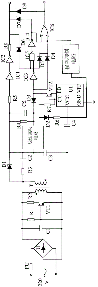
[0027] Such as figure 1 As shown, the present invention consists of a front-end rectification filter circuit, a transformer circuit connected to the front-end rectifier filter circuit, a trimming circuit and a voltage detection circuit connected to the transformer circuit, a logic control circuit connected to the trimmer circuit, and a logic control circuit The connected output circuit is composed of a linear drive circuit connected between the transformer circuit and the fine-tuning circuit, and a loss suppression circuit arranged between the voltage detection circuit and the logic control circuit.

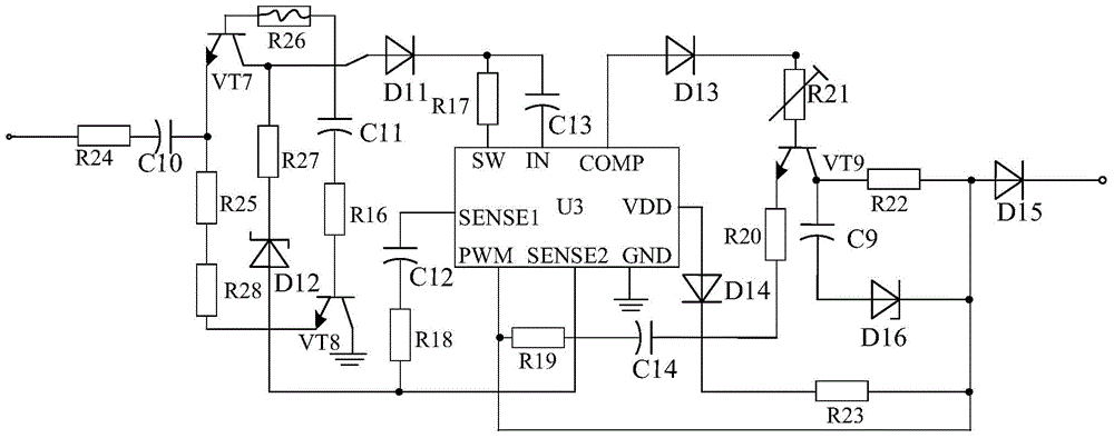
[0028] The loss suppression circuit as described in image 3As shown, by suppressing chip U3, transistor VT7, transistor VT8, transistor VT9, resistor R16, resistor R17, resistor R18, resistor R19, resistor R20, resistor R21, resistor R22, resistor R23, resistor R24, resistor R25, resistor R26, resistor R27, resistor R28, diode D11, diode D12, diode D13, diode D14, diode D15, di...


PUM


Abstract

The invention discloses a logic gate control LED system based on linear driving. The logic gate control LED system based on linear driving is mainly composed of a front-end rectification filter circuit, a voltage transformation circuit connected with the front-end rectification filter circuit, a fine adjustment circuit connected with the voltage transformation circuit, a voltage detection circuit connected with the voltage transformation circuit, a logic control circuit connected with the fine adjustment circuit, and an output circuit connected with the logic control circuit. The logic gate LED system based on linear driving is characterized in that a linear driving circuit is connected between the voltage transformation circuit and the fine adjustment circuit and is composed of a driving chip U2, a triode VT3, a triode VT4, a triode VT5, a triode VT6, a polar capacitor C6 and the like, the positive electrode of the polar capacitor C6 is connected with the voltage transformation circuit, and the negative electrode of the capacitor C6 passes through a resistor R6 and then is connected with an IN1 pin of the driving chip U2. According to the logic gate control LED system based on linear driving, due to the fact that the linear driving circuit is arranged, the LED system can be driven more stably.

Description

technical field [0001] The invention relates to an LED drive system, in particular to an LED logic gate control system based on loss suppression. Background technique [0002] As a new type of energy-saving light source, LED lights have been widely accepted and adopted by people due to their environmental protection, energy saving, long life, and small size. Since LED is a sensitive semiconductor device and has negative temperature characteristics, the LED voltage detection circuit plays a very important role in promoting the LED to be in a stable and reliable working state during the application process. [0003] However, the currently used LED drive system is susceptible to interference from the internal or external environment of the system, which affects the normal driving of the LED lamp by the system and causes the LED lamp to not work normally. Thereby affecting people's normal activities, and also affecting the service life of LED lights. Contents of the invention...

Claims


Application Information

Patent Timeline
Patent Type & Authority Applications(China)
IPC IPC(8): H05B37/02
Inventor 雷明方
Owner CHENGDU JIESHENG TECH CO LTD
Why Eureka
Try Eureka