
Battery provided with protective layer and protective layer thereof

A protective layer and battery technology, which is applied to battery components, circuits, electrical components, etc., can solve the problems of loss of power storage and discharge function of the structure, unfavorable popularization, production process requirements and high cost

Active Publication Date: 2018-09-21
赵京伟
View PDF5 Cites 0 Cited by
  • Summary
  • Abstract
  • Description
  • Claims
  • Application Information

AI Technical Summary

Problems solved by technology

However, the battery itself has requirements for the use environment. It must avoid impact and pressure resistance, and has anti-corrosion and waterproof properties. Otherwise, it will damage its own structure and lose the power storage and discharge functions. Low average will affect the performance of the battery
[0003] In some special environments, such as seawater, the battery is susceptible to seawater corrosion, low temperature affects the performance of the battery, and in the desert, the battery is easily damaged by high temperature
[0004] Various protective measures have been designed for batteries in the prior art, the most common is to stick a layer of protective film on the outer surface of the battery, which has simple waterproof and anti-corrosion effects, but the sealing and protection effect is not ideal, and it is not effective in water protective effect
Others place the battery in a protective liquid, such as an oil-immersed internal and external pressure balance battery pack. This kind of battery protection device has a complex structure, high manufacturing process requirements and high cost, which is not conducive to popularization.
[0005] There are also hard or soft packaging boxes to pack the battery. The packaging box is a metal or non-metal shell. The structure of this battery protection device is also complicated, and the sealing protection effect and temperature adjustment function are not ideal.

Method used


Image

  • Battery provided with protective layer and protective layer thereof
  • Battery provided with protective layer and protective layer thereof
  • Battery provided with protective layer and protective layer thereof

Examples


Embodiment 1

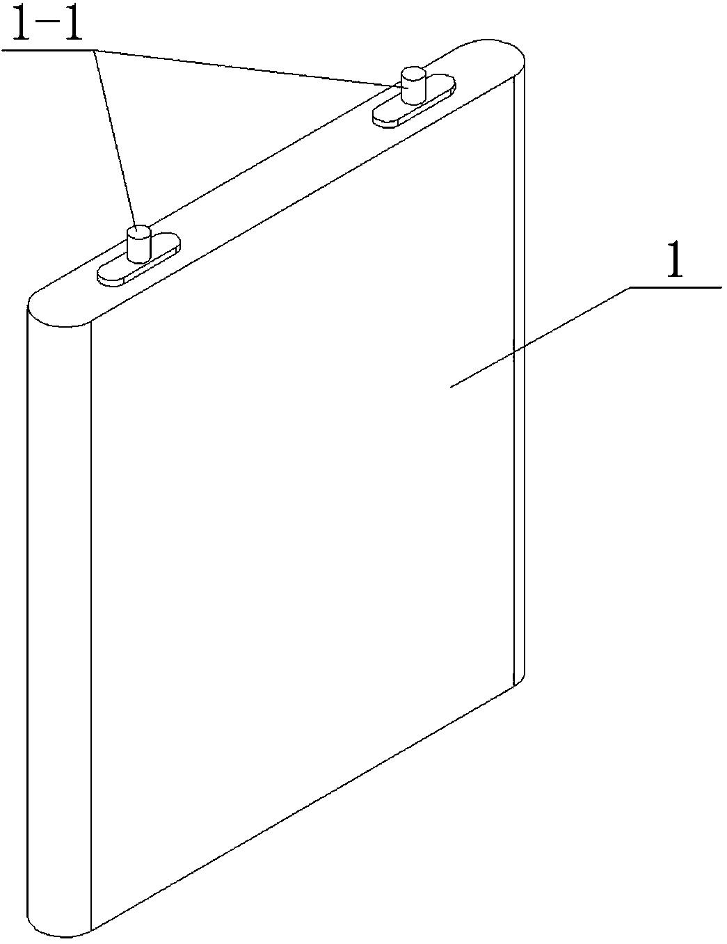
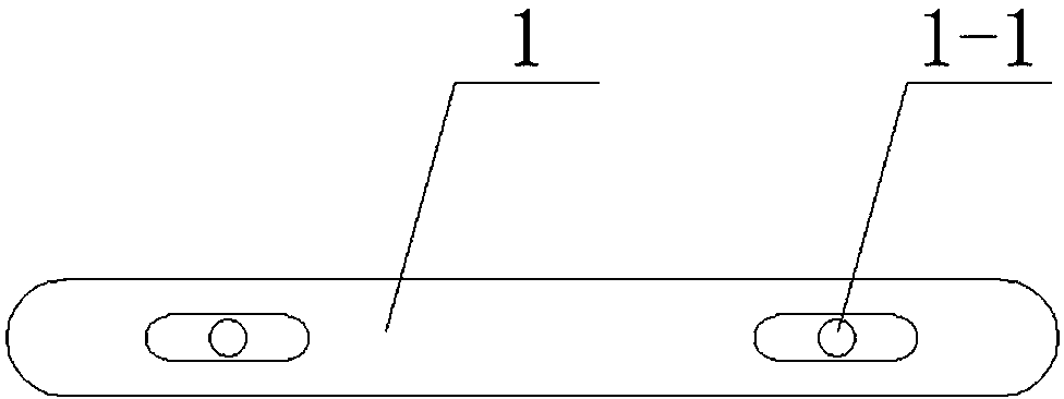
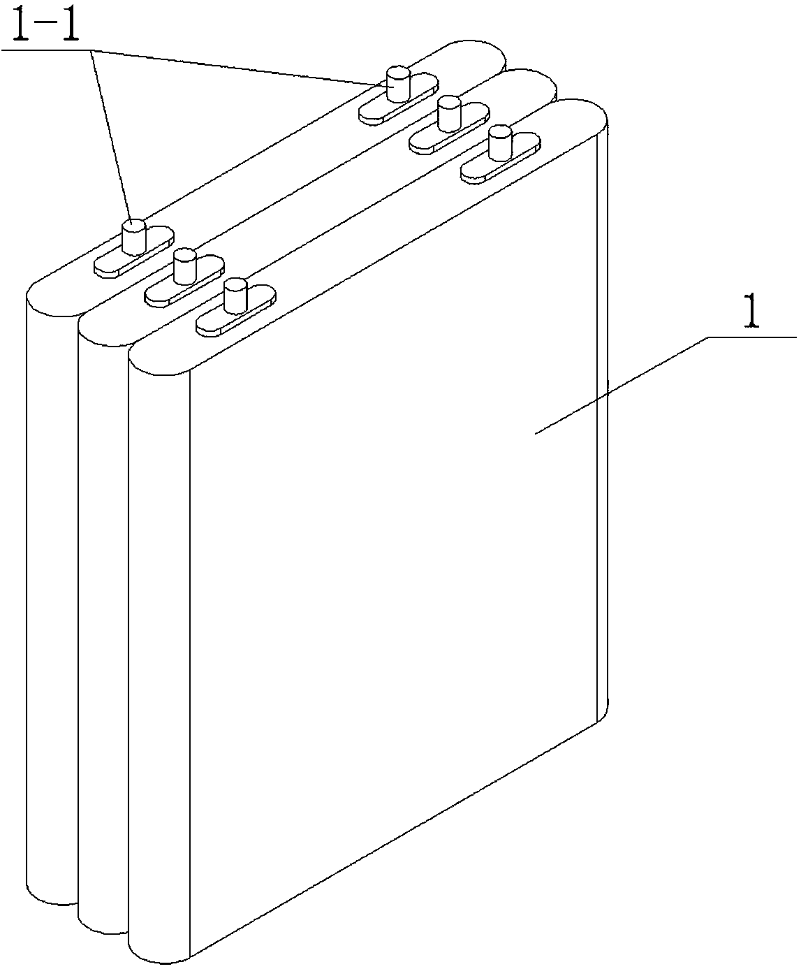
[0046] Such as Figure 8 , Figure 9 Shown is one of the embodiments of the present invention, in this embodiment, the outer surface of the battery 1 is provided with a protective layer 2, if the outer surface of the battery 1 needs to be provided with metal or non-metallic packaging, the protective layer 2 can also be arranged outside the battery On the packaging surface, the protective layer 2 is closely attached to the battery 1 or the battery outer packaging surface to seal the battery 1. The protective layer 2 is a hard layer or a soft layer, and the protective layer 2 is provided with a temperature adjustment device.

[0047] The protective layer 2 can wrap the battery 1 as a whole, including the electrodes, or can partially wrap the battery 1 except the electrodes.

[0048] The protective layer 2 can be made of materials such as silica gel or rubber, and is made on the surface of the battery 1 or the outer packaging of the battery by spraying, soaking, pasting, etc., a...

Embodiment 2

[0060] Such as Figure 10 , Figure 11 Shown is embodiment 2 of the present invention, and in this embodiment, protective layer 2 is provided with a plurality of grooves to form cooling groove 2-2, and the temperature regulating device of battery is formed by cooling groove 2-2, and cooling groove 2-2 It is mainly arranged on the upper and lower sides of the battery 1 .

[0061] Such as Figure 10 , Figure 11 As shown, the groove is in the shape of a circular groove, the depth of the groove is less than the thickness of the protective layer 2, and the bottom of the groove does not penetrate the protective layer 2, so that the temperature can be adjusted and the sealing protection performance of the protective layer 2 can be maintained. This design is only for the case where the battery needs to be cooled. The groove can also be designed as a polygonal groove.

Embodiment 3

[0063] Such as Figure 12 , Figure 13 Shown is Embodiment 3 of the present invention. In this embodiment, the protection layer 2 is provided with several grooves to form the cooling groove 2-2, and the temperature regulating device of the battery is formed by the cooling groove 2-2.

[0064] Such as Figure 12 , Figure 13 As shown, the groove is in the shape of a long groove, the depth of the groove is smaller than the thickness of the protective layer 2, and the bottom of the groove does not penetrate the protective layer 2.


PUM


Abstract

The invention discloses a protective layer for a battery. The protective layer is arranged on the surface of the battery or the outer packaging of the battery. The protective layer is closely attached to the surface of the battery or the outer packaging of the battery to seal the battery. The protective layer is a hard layer or soft layer, the protective layer is provided with a temperature regulating device. Several temperature-regulating channels are arranged inside the protective layer, and the temperature-regulating channels are provided with inlets and outlets, and the temperature-regulating device is composed of the temperature-regulating channels.

Description

technical field [0001] The invention relates to a battery provided with a protective layer, in particular to the structure of the protective layer on the outer surface of the battery. The protective layer seals and protects the battery and can play the role of impact resistance, corrosion resistance, pressure resistance, and vacuum resistance. Through the protection The layer can also regulate the operating temperature of the battery. Background technique [0002] At present, batteries are used more and more widely in various automation equipment and electronic equipment, for example, lithium-ion batteries are used as power sources. However, the battery itself has requirements for the use environment. It must avoid impact and pressure resistance, and has anti-corrosion and waterproof properties. Otherwise, it will damage its own structure and lose the power storage and discharge functions. Low average will affect the performance of the battery. [0003] In some special env...

Claims


Application Information

Patent Timeline
Patent Type & Authority Patents(China)
IPC IPC(8): H01M2/02H01M50/121H01M50/14H01M50/145
CPCH01M50/124H01M50/1245Y02E60/10
Inventor 赵京伟
Owner 赵京伟
Learn More