
Signal transmission line structure and electronic device for its application

A technology for signal transmission lines and electronic devices, applied to printed circuit components and other directions, can solve the problems of limited overall volume and difficult design of transmission lines, and achieve the effect of reducing chip area, reducing signal transmission length, and low resistance value.

Active Publication Date: 2018-04-13
REALTEK SEMICON CORP
View PDF3 Cites 0 Cited by
  • Summary
  • Abstract
  • Description
  • Claims
  • Application Information

AI Technical Summary

Problems solved by technology

However, the size of electronic devices has been tending to be thinner and smaller, but in order to maintain the signal quality, the size of the signal transmission line structure is difficult to reduce, so that the overall volume is limited
The metal layer of another advanced process is getting thinner and thinner. If only multi-layer metal layer stacking is implemented, it will make the design of the transmission line more difficult.

Method used


Image

  • Signal transmission line structure and electronic device for its application
  • Signal transmission line structure and electronic device for its application
  • Signal transmission line structure and electronic device for its application

Examples


Embodiment Construction

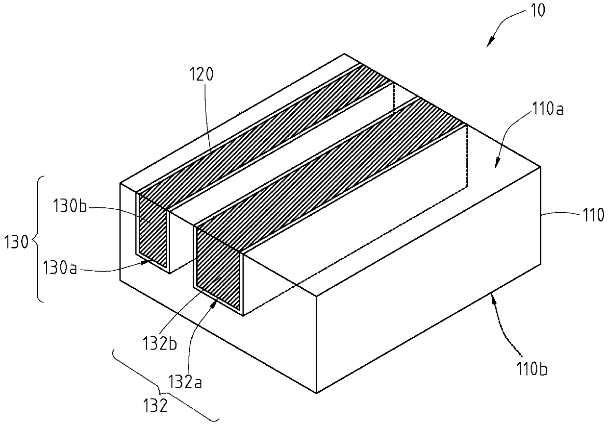
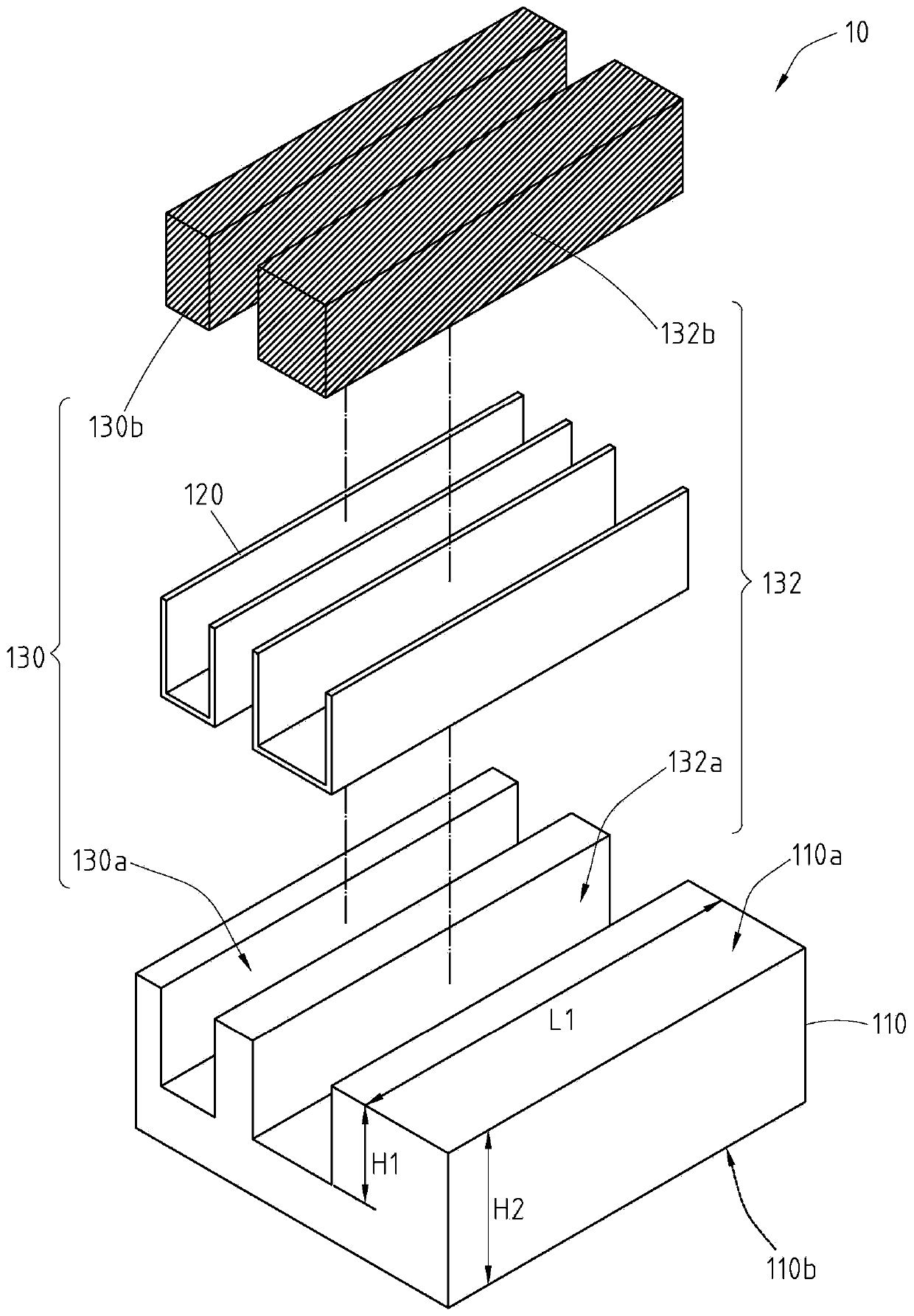
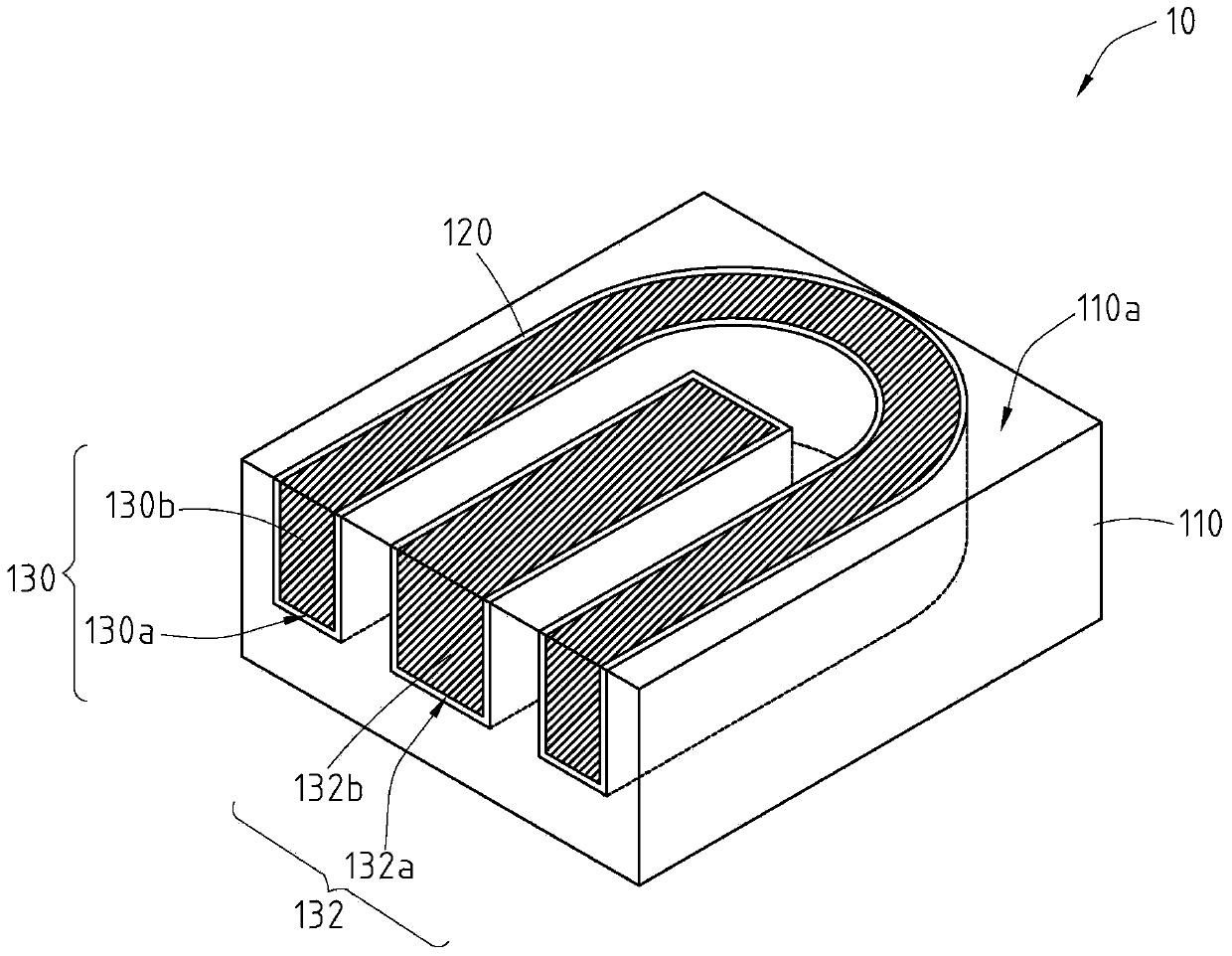
[0072] refer to figure 1 and 2 The signal transmission line structure 10 includes: a substrate 110 , a plurality of through-silicon via (TSV) trenches 130 a, 132 a, and conductive substances 130 b, 132 b. Two TSV trenches are taken as an example below.

[0073] The substrate 110 has a first surface 110a and a second surface 110b, and the first surface 110a and the second surface 110b are opposed to each other. In other words, the first surface 110a of the substrate 110 is the upper surface, and the second surface 110b of the substrate 110 is the lower surface.

[0074]TSV trenches 130 a and 132 a are formed on the first surface 110 a of the substrate 110 . Each TSV trench 130a, 132a extends its length L1 along the first surface 110a. In other words, the TSV trenches 130a, 132a are elongated.

[0075] Each TSV trench 130 a , 132 a extends downwards (towards the second surface 110 b ) to a depth H1 from the first surface 110 a , but does not penetrate the substrate 110 . H...


PUM


Abstract

The invention relates to a signal transmission line structure and an electronic device for its application. A signal transmission line structure includes a substrate, a plurality of through-silicon via (TSV) trenches, a conductive substance, at least one conductive line and a dielectric layer. The substrate has a first surface and a second surface opposite to each other. The TSV trench is formed on the first surface of the substrate and extends along the first surface. The bottom surface of the TSV trench is located between the first surface and the second surface of the substrate. Conductive material fills the TSV trenches to form transmission lines. Conductive lines are located above the transmission lines. The dielectric layer is located on the first surface of the substrate and separates the conductive line and the transmission line.

Description

technical field [0001] The present invention relates to a structural design of a microstrip line (microstrip), in particular to a signal transmission line structure and an electronic device for its application. Background technique [0002] At present, due to the rapid development and wide demand of wireless communication technologies such as wireless networks, mobile phones, Global Positioning System (GPS), and digital TV, the design and manufacture of high-speed digital circuits has become an extremely important task in the communication industry. Hot electronic technology. Basically, most high-speed digital circuits use microstrip or stripline as signal transmission lines to transmit high-speed digital signals. At present, the electronics industry has developed many different circuit board structures for high-speed digital signal transmission. [0003] In the known signal transmission line structure, two metal layers corresponding to each other are respectively formed o...

Claims


Application Information

Patent Timeline
Patent Type & Authority Patents(China)
IPC IPC(8): H05K1/02
Inventor 颜孝璁简育生叶达勋
Owner REALTEK SEMICON CORP
Learn More