
Method and device for continuous time difference measurement

A time difference and clock technology, applied in the field of time difference measurement, can solve the problems of high cost, limited speed and range, limited speed and accuracy of measurement, etc.

Inactive Publication Date: 2018-07-17
刘伯安
View PDF4 Cites 0 Cited by
  • Summary
  • Abstract
  • Description
  • Claims
  • Application Information

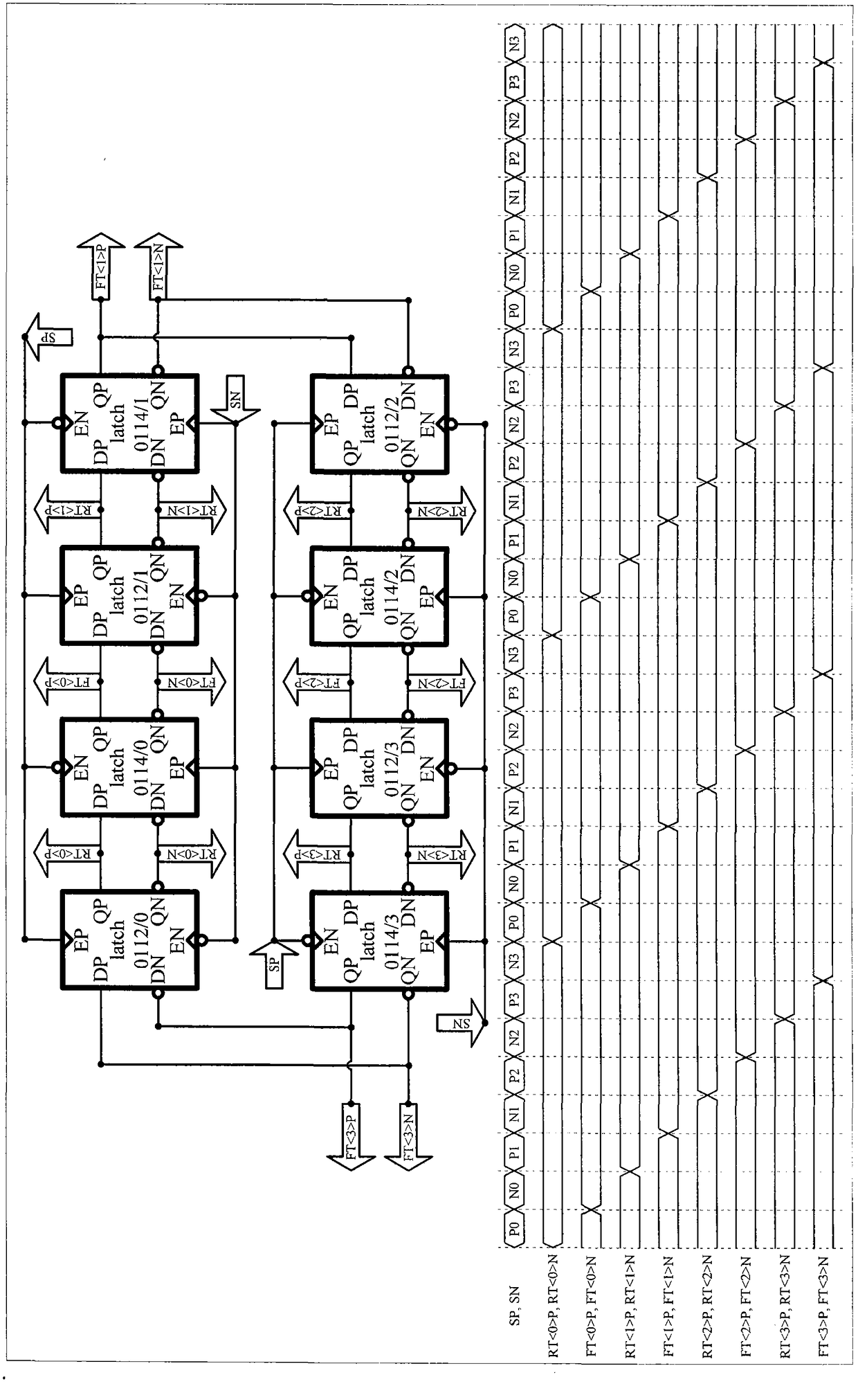
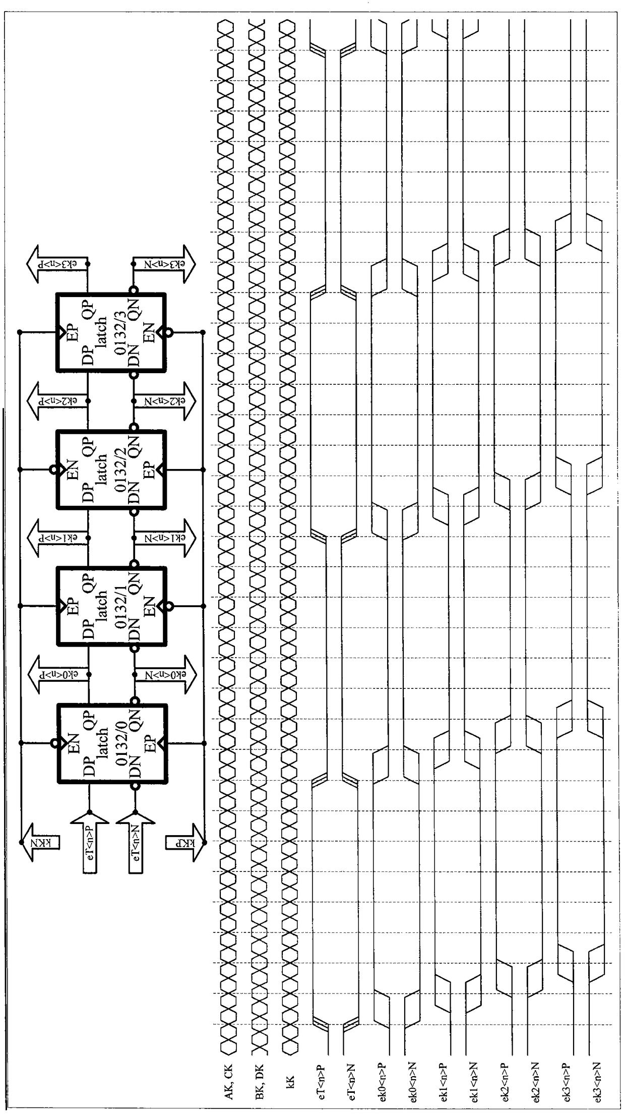
AI Technical Summary

Problems solved by technology

[0002] Perceiving the time and order of appearance of natural phenomena is one of the basic means to understand nature. Time difference measurement (0000) is a necessary means to perceive time and order. In general, the speed, accuracy, range, cost, etc. of time difference measurement (0000) Requirements are not the same, often can not be taken into account, for example, the accuracy and range of high-speed measurement are limited, the speed and range of high-precision measurement are limited, the speed and accuracy of wide-range measurement are limited, high speed, high precision, wide range means with higher costs, etc.

Method used


Image

  • Method and device for continuous time difference measurement
  • Method and device for continuous time difference measurement
  • Method and device for continuous time difference measurement

Examples


Embodiment Construction

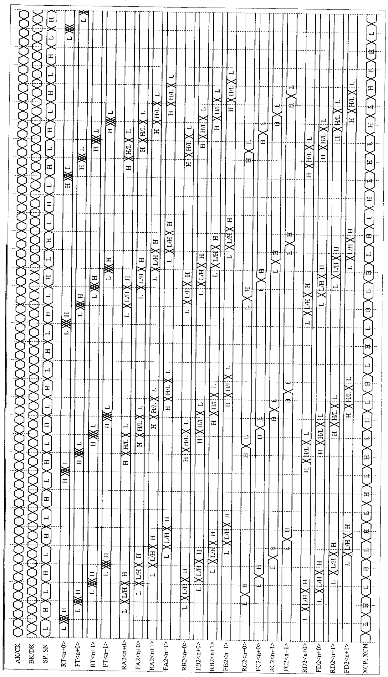
[0009] In the following, the method of the present invention will be described first, then the circuit of the preferred example for applying the method of the present invention will be described, and then the device of the preferred example for applying the method of the present invention will be described.

[0010] In the drawings, the substrates of the MOS transistors are not marked, and it is agreed that the substrates of the NMOS transistors are connected to the ground line GND, and the substrates of the PMOS transistors are connected to the power supply VDD.

[0011] In the accompanying drawings and this specification, the gate signal of the latch (0040) is represented by E (EP, EN). When EP is high level (H) and EN is low level (L), the latch The output Q (QP, QN) of (0040) is equal to the input D (DP, DN). When EP is low level (L) and EN is high level (H), the output Q ( QP, QN) remain unchanged.

[0012] In the accompanying drawings and this specification, many electr...


PUM


Abstract

The present invention provides an equal time delay signal conversion method and device which can realize the continuous measurement of the duration time of a high level or a low level of an electronic signal and the time interval of the rising edge-to-rising edge or falling edge-to-falling edge, also provides a method and device applying to the flight time measurement, the laser ranging and the like, and also provides some methods and devices applying to the serial data reception, thereby reducing the sensitivity to the clock frequency, the distortion, the jitter and the like, and enabling a serial data reception device to be more reliable and to be easy to realize.

Description

technical field [0001] The present invention generally relates to methods and devices for time difference measurement (0000), such as methods and devices for time difference sampling, methods and devices for continuous time difference measurement, etc., including pulse width measurement, pulse period measurement, time of flight measurement, pulse ranging, serial Data reception, etc. Specifically, the present invention relates to a method and device for continuous time difference measurement (0000) with high speed, high precision and wide range. Based on the method and device, various measuring devices and systems can be realized with low cost and high performance, satisfying Time-of-flight measurement, pulse ranging, serial data reception and other requirements. Background technique [0002] Perceiving the time and order of appearance of natural phenomena is one of the basic means to understand nature. Time difference measurement (0000) is a necessary means to perceive time...

Claims


Application Information

Patent Timeline
Patent Type & Authority Patents(China)
IPC IPC(8): H03K23/40G04F10/04
Inventor 刘伯安
Owner 刘伯安
Learn More