A clamping device for optical fiber and lithium niobate wafer

A clamping device, lithium niobate technology, applied in the field of clamps, can solve the problems of large Fresnel reflection, strong noise optical signal, affecting the accuracy of the gyroscope, etc., and achieve the effect of stable clamping and simple operation

Inactive Publication Date: 2017-05-24
BEIHANG UNIV
View PDF4 Cites 0 Cited by
  • Summary
  • Abstract
  • Description
  • Claims
  • Application Information

AI Technical Summary

Problems solved by technology

In SiO 2 Materials for optical fibers (fibers in LiNbO 3 wafer slot) with LiNbO 3 At the coupling interface of the waveguide of the material, due to the large difference in the refractive index of the material, there will be a large Fresnel reflection. If a general optical fiber is coupled with the vertical end face of the optical waveguide, the reflected light will propagate backward along the fiber core. , forming a strong noise optical signal, seriously affecting the accuracy of the gyroscope

Method used


Image

  • A clamping device for optical fiber and lithium niobate wafer
  • A clamping device for optical fiber and lithium niobate wafer
  • A clamping device for optical fiber and lithium niobate wafer

Examples


Embodiment Construction

[0031] The present invention will be further described in detail below in conjunction with the accompanying drawings.

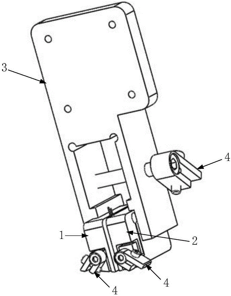
[0032] The optical fiber and lithium niobate wafer clamping device of the present invention comprises a left base 1, a right base 2, a base clamping member 3 and a locking mechanism 4, such as figure 1 shown.

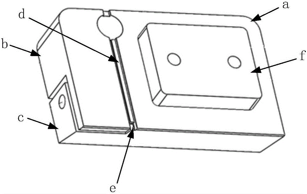
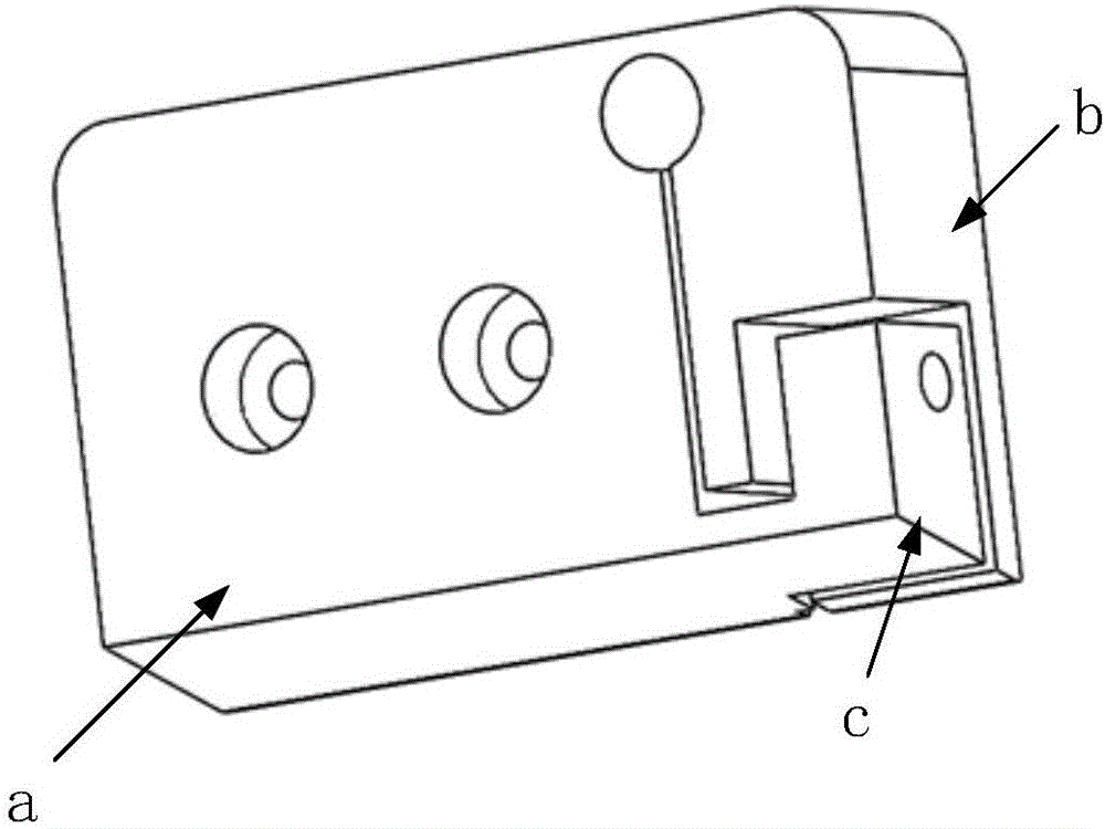
[0033] Among them, the left base 1 and the right base 2 are arranged symmetrically on the left and right, and are both an integrated rectangular block structure composed of a positioning block a, a clamping block b and a loading block c, and are made of AISI 321 annealed stainless steel.

[0034] Such as figure 2 , image 3 As shown, in the left base 1, the positioning block a is used as a non-deformable unit, and a rectangular protrusion f is designed on the right side, which is used to cooperate with the rectangular recess g designed on the left side of the positioning block a in the right base 2. The positioning between the left base 1 and the r...


PUM


Abstract

The invention discloses an optical fiber and lithium niobate wafer clamping device. The optical fiber and lithium niobate wafer clamping device comprises a left base, a right base and base clamping pieces. The left base and the right base are arranged in a lateral symmetry mode and each composed of a positioning block, a clamping block and a loading block. The tops of the rear side faces of the clamping blocks are connected with the tops of the front side faces of the positioning blocks, and gaps are formed between the rear side faces of the clamping blocks and the front side faces of the positioning blocks. The bottoms of the rear side faces of the loading blocks are connected with the bottoms of the front side faces of the positioning blocks. Optical fiber positioning grooves penetrating through the upper side faces and the lower side faces of the positioning blocks are designed in the right side faces of the positioning blocks. One end of each optical fiber positioning groove is provided with a wafer positioning groove which is located at the bottom of the corresponding positioning block. The screw loading blocks make contact with the lower sides of the front portions of the clamping blocks, clamping screws are screwed up and push the lower portions of the clamping blocks backwards, and wafers are clamped in the wafer positioning grooves through the rear side faces of the clamping blocks. The left base and the right base are integrated through clamping of the base clamping pieces. The optical fiber and lithium niobate wafer clamping device has the advantages that the two lithium niobate wafers can be repeatedly clamped, and operation is simple.

Description

technical field [0001] The invention relates to a jig, in particular to a fast and stable clamping device for a polarization-maintaining optical fiber and a lithium niobate wafer for an optical fiber gyroscope. Background technique [0002] The lithium niobate integrated optical phase modulation device used in the fiber optic gyroscope (referred to as a multifunctional integrated optical chip abroad, MFIOC) refers to a waveguide device that contains the functions of a Y-shaped beam splitter, a polarizer and a phase modulator. The functional components are integrated on the same chip, and its excellent characteristics ensure the realization of high-performance digital closed-loop fiber optic gyroscope. [0003] The input and output of the waveguide light is realized by direct coupling with the end face of the pigtail. In order to obtain low optical coupling loss, LiNbO 3 (lithium niobate) wafers and fiber end faces for high-quality polishing. In SiO 2 Materials for optical...

Claims


Application Information

Patent Timeline
Patent Type & Authority Patents(China)
IPC IPC(8): B24B37/30
CPCB24B37/30
Inventor 李慧鹏张轩宋凝芳高爽朱伟伟郑晓
Owner BEIHANG UNIV
Why Eureka
Try Eureka