


Quick Research
Generate reliable direction feasibility study reports for your R&D in just a few steps.

Technical Q&A
Discover and master advanced knowledge NOW. Basics, ideas, possibilities, all at once.

Find Solutions
As an expert in R&D theories, this can generate solutions to your technical problems instantly.

Evaluate Feasibility
Analyze your overall solution with one click, know your potential R&D risks in advance.

Monitor Landscape
Get weekly tech updates, stay abreast of the latest tech innovations and key insights.
Equipment and process for forming bicycle aluminum alloy upright pipe
A molding equipment, aluminum alloy technology, applied in molding tools, bicycle accessories, metal processing equipment, etc., can solve the problems of large differences in product dimensions, low molding yield rate, complicated equipment processing, etc., to achieve weight reduction and good molding. The effect of high rate and lower production cost
- Summary
- Abstract
- Description
- Claims
- Application Information
AI Technical Summary
Problems solved by technology
Method used
Image

Examples
Embodiment 1
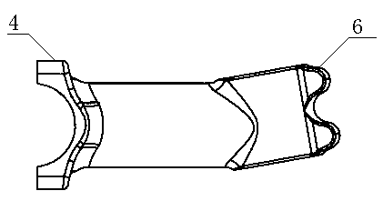
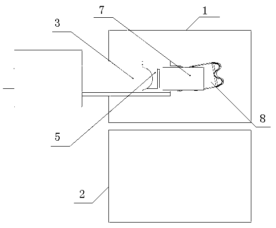
[0021] see figure 1 , figure 2 As shown, a bicycle aluminum alloy riser forming equipment includes a riser shape mold and a hydraulic punch mechanism, and the riser shape mold includes a structurally symmetrical upper mold 1 and a lower mold 2, and the upper mold 1 and the lower mold 2 are closed to form a bicycle aluminum alloy riser mold cavity 8 in the middle, the front end of the bicycle aluminum alloy riser mold cavity 8 is a closed end and the shape of the bicycle aluminum alloy riser head 6, the rear end It is an open end; the hydraulic punch mechanism includes a retractable main punch 3, the front end of the main punch 3 is shaped like the tail part 4 of a bicycle aluminum alloy riser, and inside the main punch 3 is a A retractable sub-punch 5; the hydraulic punch mechanism can be inserted into the bicycle aluminum alloy standpipe cavity 8 from the open end of the bicycle aluminum alloy standpipe cavity 8.
Embodiment 2
[0023] see figure 1 , figure 2 Shown: a forming process of a bicycle aluminum alloy standpipe, which includes the following steps:
[0024] Step 1) Clamping the upper mold 1 and the lower mold 2 to form the mold cavity 8 of the bicycle aluminum alloy stand pipe;
[0025] Step 2) Putting a solid aluminum billet 7 into the mold cavity 8 of the bicycle aluminum alloy stand pipe;
[0026] Step 3) The hydraulic punch mechanism is inserted into the mold cavity 8 of the bicycle aluminum alloy standpipe, and the aluminum blank 7 is squeezed so that the front end of the aluminum blank 7 squeezes the bicycle aluminum alloy standpipe The closed end of the mold cavity 8 causes the front end of the aluminum billet 7 to be shaped into the shape of the bicycle aluminum alloy riser head 6;
[0027] Step 4) The main punch 3 unloads and retreats to the set position, and at the same time, the sub-punch 5 continues to push into the mold cavity 8 of the bicycle aluminum alloy riser, causing th...
PUM
 Abstract
Description
Claims
Application Information
 - R&D Engineer
- R&D Manager
- IP Professional
- Industry Leading Data Capabilities
- Powerful AI technology
- Patent DNA Extraction
Browse by: Latest US Patents, China's latest patents, Technical Efficacy Thesaurus, Application Domain, Technology Topic, Popular Technical Reports.
© 2024 PatSnap. All rights reserved.Legal|Privacy policy|Modern Slavery Act Transparency Statement|Sitemap|About US| Contact US: help@patsnap.com