
Reducing insertion loss in LNA bypass mode by using a single-pole-triple-throw switch in a RF front end module

A front-end module, single-pole, three-throw technology, used in transmission systems, electrical components, etc.

Active Publication Date: 2015-10-07
MICROCHIP TECH INC
View PDF3 Cites 13 Cited by
  • Summary
  • Abstract
  • Description
  • Claims
  • Application Information

AI Technical Summary

Problems solved by technology

The overall insertion loss of this LNA bypass configuration typically exceeds 3dB due to the two switches connected in series

Method used


Image

  • Reducing insertion loss in LNA bypass mode by using a single-pole-triple-throw switch in a RF front end module
  • Reducing insertion loss in LNA bypass mode by using a single-pole-triple-throw switch in a RF front end module
  • Reducing insertion loss in LNA bypass mode by using a single-pole-triple-throw switch in a RF front end module

Examples


Embodiment Construction

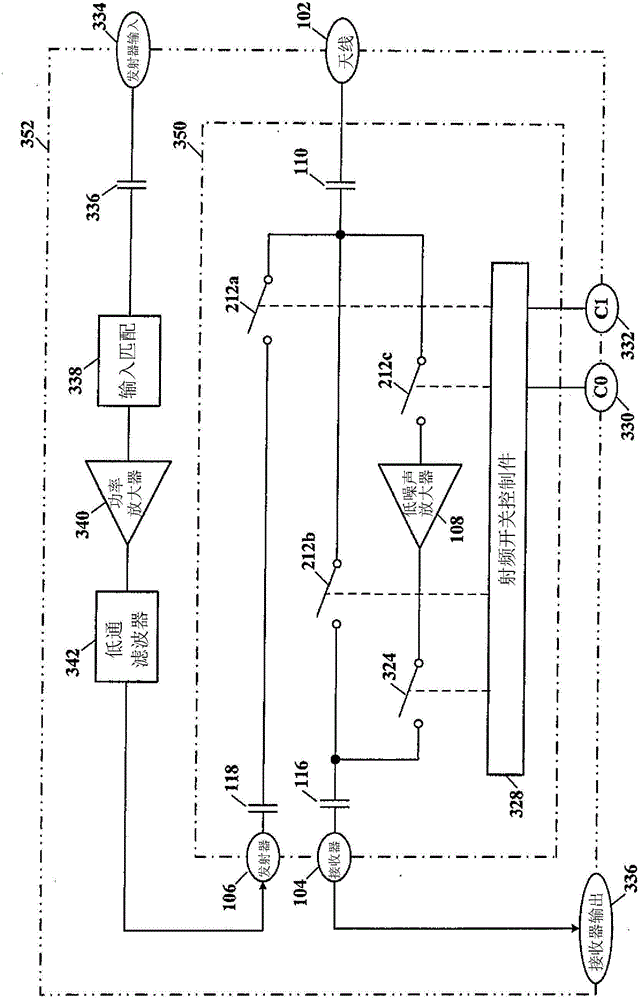
[0018] By using a single pole three throw switch, the received RF signal travels through only one RF signal switching device, thereby reducing the insertion loss to about 1 dB. Therefore, the RF receiver sensitivity is significantly improved when the LNA is in bypass mode.

[0019] Referring now to the drawings, details of certain example embodiments are schematically illustrated. Like elements in the drawings will be represented by the same number, and similar elements will be represented by the same number with a different lowercase letter suffix.

[0020] Referring to FIG. 1 , depicted is a schematic diagram of a conventional bypass circuit for an LNA using two series-connected single pole double throw switches. Low noise amplifier (LNA) 108 has a bypass option implemented with two single pole double throw (SPDT) radio frequency (RF) switches 112 and 114 connected in series along the receive signal path. The overall insertion loss of this LNA bypass configuration typicall...


PUM


Abstract

A microwave radio frequency (RF) front end module (FEM) having a low noise amplifier (LNA) with a bypass mode uses a single-pole-triple-throw RF switch that reduces insertion loss to about 1 dB and thereby improves RF receiver sensitivity over existing technology two series connected single-pole-double throw RF switches. The single-pole-triple-throw RF switch may be three metal oxide semiconductor field effect transistor (MOSFET) RF switches that may be arranged with a common source input and isolated independent drain outputs. The RF switches may be single, double or triple gate MOSFET RF switches. The MOSFET RF switches may also be configured as complementary metal oxide semiconductor (CMOS) field effect transistor (FET) RF switches.

Description

technical field [0001] The present invention relates to radio frequency (RF) devices, and more particularly to reducing insertion loss in low noise amplifier (LNA) bypass mode by using a single pole three throw switch in an RF front end module (FEM) of the RF device. Background technique [0002] RF FEMs serving both transmit and receive modes of an RF device typically employ a low noise amplifier (LNA) with a bypass option implemented with two single pole double throw (SPDT) switches connected in series along the receive signal path. The overall insertion loss of this LNA bypass configuration typically exceeds 3dB due to the two switches connected in series. Contents of the invention [0003] Therefore, there is a need for improved ways to provide LNA bypass switch configurations with less insertion loss. [0004] According to an embodiment, a radio frequency (RF) front-end module (FEM) may include: a low-noise amplifier (LNA) having an input and an output; and a single-...

Claims


Application Information

Patent Timeline
IPC IPC(8): H04B1/00H04B1/40
CPCH04B1/44H04B1/006H04B1/406
Inventor 永林·柯
Owner MICROCHIP TECH INC
Learn More