Coupling device between fluid reservoir and master brake cylinder of motor vehicle braking system

一种联接装置、制动系统的技术,应用在液压制动传动装置、水库的布置、连接等方向,能够解决连接螺栓易变松、不可靠、失效等问题,达到不易失效、消除组装错误、改进组装容易性的效果

Inactive Publication Date: 2017-09-08
LUCAS AUTOMOTIVE GMBH
View PDF3 Cites 0 Cited by
  • Summary
  • Abstract
  • Description
  • Claims
  • Application Information

AI Technical Summary

Problems solved by technology

This solution is unreliable because the connecting bolts are relatively easy to loosen and then fail

Method used


Image

  • Coupling device between fluid reservoir and master brake cylinder of motor vehicle braking system
  • Coupling device between fluid reservoir and master brake cylinder of motor vehicle braking system
  • Coupling device between fluid reservoir and master brake cylinder of motor vehicle braking system

Examples


Embodiment Construction

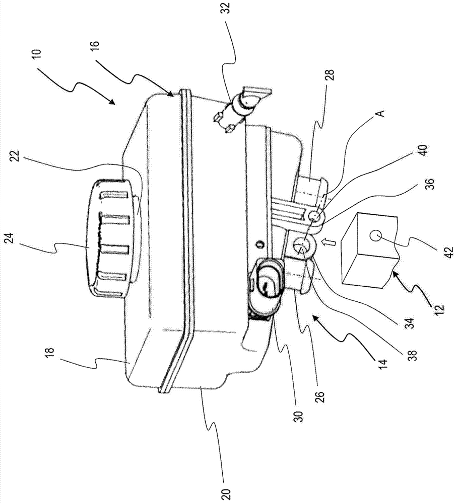
[0027] figure 1 A three-dimensional view is shown of a fluid reservoir 10 for mounting on a brake master cylinder, which is not shown in detail. On the master brake cylinder there is integrally formed a mounting part 12 which is connected to a fluid reservoir 10 by means of a coupling means 14, as will be described in detail below.

[0028]The fluid reservoir 10 is provided with a fluid container 16 consisting of two hollow bodies 18 , 20 which are welded to each other. The upper hollow body 18 has a filling neck 22 which provides access for replenishment and which can be closed by means of a cover 24 . The lower hollow body 20 has two connectors 26 , 28 on its underside, by means of which the lower hollow body can be fluid-tightly coupled to the master brake cylinder in a known manner. No further details were provided on this. Also evident on the lower hollow body 20 are the electrical connection sockets 30 of the fill level measuring device and a further filling neck 32 f...


PUM


Abstract

The invention relates to a coupling device between a fluid reservoir (10) and a master brake cylinder, wherein two coupling arms (34, 36) each having a coupling opening (38, 40) are arranged on one of the parts , and on the other part is arranged a mounting part (12) with a receiving hole (42), the two coupling arms (34, 36) are engaged on the mounting part (12) such that the coupling opening (38, 40) and said receiving hole (42) are aligned relative to each other along a common axis (A), wherein in order to couple said mounting part (12) to said two coupling arms, a The coupling pin (46) is inserted into the opening (38, 40) and said receiving hole (42), and is fixed relative to at least one coupling arm (34, 36) or said mounting portion (12), wherein said The coupling pin (46) is formed with a cylindrical shank and at least one radially protruding locking protrusion (48).

Description

technical field [0001] The invention relates to a coupling device for a motor vehicle braking system between a fluid reservoir and a master brake cylinder, wherein a coupling hole is arranged on a part of the fluid reservoir or the master brake cylinder Two coupling arms, wherein on the other part of the fluid reservoir or the master brake cylinder, a mounting part with a receiving hole is arranged, wherein the two coupling arms contact the mounting part, so that in the mounted state, the coupling hole and the receiving holes are aligned with each other along a common axis, wherein in order to couple the mounting part to the two coupling arms, a coupling bolt can be inserted into the coupling hole and the receiving hole and can be fixed relative to at least one of the coupling arms or the mounting part, In this case, the coupling bolt is configured with a cylindrical shank and at least one radially protruding locking projection. Background technique [0002] Among the types...

Claims


Application Information

Patent Timeline
Patent Type & Authority Patents(China)
IPC IPC(8): B60T11/26B60T17/06
CPCB60T17/06B60T11/22B60T11/26Y10T403/7075
Inventor H·C·兰格
Owner LUCAS AUTOMOTIVE GMBH
Why Eureka
Try Eureka