Method for measuring thickness of transparent spherical cavity container

A measurement method, spherical technology, applied in the field of optical measurement, can solve problems that are not easy to achieve

Inactive Publication Date: 2015-10-07
NANKAI UNIV
View PDF4 Cites 0 Cited by
  • Summary
  • Abstract
  • Description
  • Claims
  • Application Information

AI Technical Summary

Problems solved by technology

The phase method involves frequency modulation technology, which is not easy to implement

Method used


Image

  • Method for measuring thickness of transparent spherical cavity container
  • Method for measuring thickness of transparent spherical cavity container
  • Method for measuring thickness of transparent spherical cavity container

Examples


Embodiment Construction

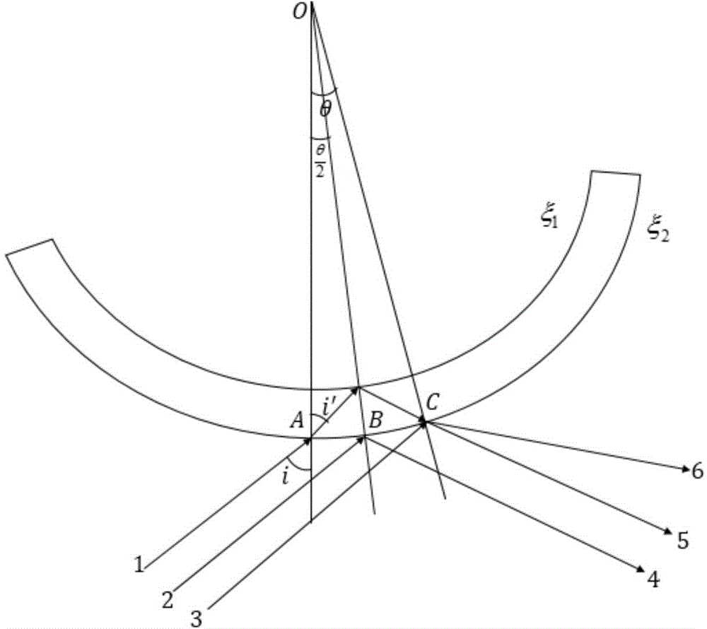
[0027] Such as figure 1 As shown, ξ 1 is the inner surface of the container, ξ 2 for the outer surface of the container. Incident rays 1, 2, 3 represent incident laser beams. Since the directionality of the laser is very good, it can be considered theoretically that the incident rays 1, 2, and 3 are parallel rays. OA, OB, OC are the normals of different incident positions on the inner and outer surfaces of the container. The refractive index of the dielectric layer is n. The incident light 1 enters the medium layer after being refracted by the outer surface, and is refracted from the outer surface after being reflected by the inner surface to form an outgoing light 5 . The incident ray 2 is reflected by the outer surface of the container as reflected ray 4 . Incident light 3 becomes reflected light 6 after being reflected by the outer surface.

[0028] The angle between the incident ray 1 and the normal OA is i, that is, the incident angle is i, and the refraction angle...


PUM


Abstract

The invention discloses a method for measuring thickness of a transparent spherical cavity container. The method is based on the interference principle of light, and a relation of object thickness and an interference pattern is determined mainly through the light field interference phenomenon. The system of the method is composed of a helium neon laser, a beam expanding system, a half transparent and half reflecting mirror, an aperture diaphragm, a reception screen, a measuring guide rail, an objective table and a transparent spherical cavity container. The laser generated by the helium neon laser is reflected to the surface of the transparent spherical cavity container through the half transparent and half reflecting mirror first, then light is reflected by the inner surface and the outer surface of the transparent spherical cavity container to the reception screen and an interference field is generated; striped patterns in the interference field are received and measured, and therefore information of the interference field is extracted. The method can achieve non-contact lossless measurement of thickness of the transparent spherical cavity container. During the measuring process, other auxiliary measuring modes of film plating, liquid injection and the like are not needed, and the method has characteristics of simple device, strong operationality and the like.

Description

technical field [0001] The invention belongs to the technical field of optical measurement, and relates to a method for realizing non-contact non-destructive measurement of the thickness of a transparent spherical cavity container by using light field interference. Background technique [0002] At present, the main thickness measurement methods in life and industry include direct measurement method, Hall effect thickness measurement method, ultrasonic thickness measurement method, phase method and so on. [0003] The direct measurement method is to use ruler, vernier caliper, measuring microscope, spiral micrometer, etc. to directly measure the thickness of the object. It is generally suitable for non-enclosed objects with a thickness of tens of microns or more and a flat surface. [0004] The Hall effect thickness gauge mainly uses a steel ball and a probe to measure the thickness. The steel ball is placed on one side of the object, and the probe is used to measure on the ...

Claims


Application Information

Patent Timeline
Patent Type & Authority Applications(China)
IPC IPC(8): G01B11/06
Inventor 王晓雷李宏勋朱博文
Owner NANKAI UNIV
Why Eureka
Try Eureka