
Solar heat-complementary combined cycle power generation system

A combined cycle power generation and solar thermal technology, which is applied in the direction of combined combustion mitigation, machine/engine, steam engine device, etc., can solve problems affecting the thermal efficiency of collectors, achieve high thermodynamic advantages and economic advantages, and high solar thermal power conversion Efficiency, Simplification of the Effects of the Trough Solar Subsystem

Active Publication Date: 2015-10-07
NORTH CHINA ELECTRIC POWER UNIV (BAODING)
View PDF5 Cites 19 Cited by
  • Summary
  • Abstract
  • Description
  • Claims
  • Application Information

AI Technical Summary

Problems solved by technology

[0003] The traditional solar thermal complementary combined cycle system uses heat transfer oil or molten salt as the heat exchange medium of its trough solar subsystem, and the integrated temperature of the trough solar subsystem is limited by the physical properties of the heat exchange medium; At the same time, the heat exchange working medium needs to be heated by electric heating or steam extraction to reach the minimum start-up operating temperature of the heat exchange working medium; at the same time, the heat exchange working medium can decompose and produce hydrogen and other gases after long-term operation, which directly affects the thermal efficiency of the collector

Method used


Image

  • Solar heat-complementary combined cycle power generation system
  • Solar heat-complementary combined cycle power generation system
  • Solar heat-complementary combined cycle power generation system

Examples


Embodiment Construction

[0011] The present invention proposes a solar thermal complementary combined cycle power generation system, which will be described in detail below in conjunction with the accompanying drawings and specific embodiments.

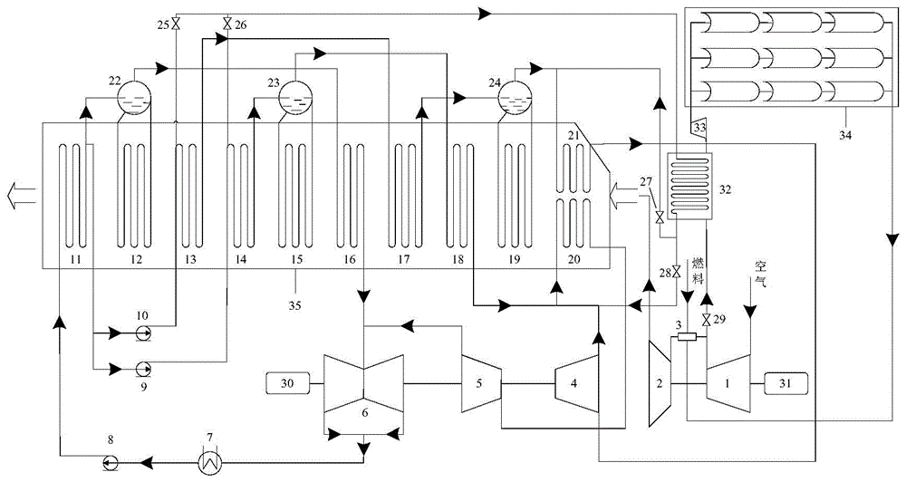
[0012] figure 1 Shown is a schematic diagram of the solar thermal complementary combined cycle power generation system proposed by the present invention, the gas turbine compressor 1 is connected to the gas turbine turbine 2 through the gas turbine combustion chamber 3; the gas turbine compressor 1, the gas turbine turbine 2, and the second power generation The engine 31 is coaxially connected; the outlet of the gas turbine compressor 1 passes through the fifth regulating valve 29, the air-water heat exchanger 32, the cold air compressor 33, the trough-type concentrating and heat-collecting mirror field 34, and the combustion chamber 3 of the gas turbine. The inlet is connected; the outlet of the gas turbine 2 is connected to the inlet of the triple-pressure ...


PUM


Abstract

The invention discloses a solar heat-complementary combined cycle power generation system and belongs to the technical field of solar and gas turbine combined cycle power generation. A fifth adjusting valve, a gas-water heat exchanger, a cold air compressor, a trough concentrating and heat collecting mirror field form a trough solar sub system; by adopting gas turbine compressed air as a heat transfer medium, the integration temperature is not limited by physical properties of a heat transfer medium any longer; when the system works under a medium pressure integration mode, feed water at the outlet of a medium pressure feed pump is divided into two strands, one strand of water flows in a medium pressure economizer while the other strand of water is controlled by virtue of a second adjusting valve and a forth adjusting valve; when the system works under a high pressure integration mode, feed water at the outlet of a high pressure feed pump is divided into two strands, one strand of water flows in a first-stage high pressure economizer while the other strand of water is controlled by a first adjusting valve and a third adjusting valve; and air after being subjected to heat collection is injected into a gas turbine combustor so as to ensure relatively high solar heat-to-electricity efficiency. Compared with the tradtional solar heat-complementary combined cycle power generation system, the solar heat-complementary combined cycle power generation system disclosed by the invention has high thermodynamic and economic advantages.

Description

technical field [0001] The invention belongs to the technical field of solar energy and gas turbine combined power generation, and in particular relates to a solar thermal complementary combined cycle power generation system. Background technique [0002] The massive consumption of primary energy not only causes environmental pollution such as smog, but also produces a large amount of greenhouse gas CO 2 In the face of global environmental problems such as environmental pollution and the greenhouse effect, when countries formulate energy development routes, they all focus on renewable energy. Integrating solar thermal power generation technology with mature conventional power generation technology for multi-energy complementary power generation can reduce the technical and economic risks of developing and utilizing solar energy, effectively solve technical bottlenecks such as unstable solar energy utilization and immature heat storage technology, and achieve high efficiency....

Claims


Application Information

Patent Timeline
Patent Type & Authority Applications(China)
IPC IPC(8): F02C6/18F02C7/08F01K23/10
CPCY02E20/16
Inventor 段立强曲万军乐龙夏堃杨勇平
Owner NORTH CHINA ELECTRIC POWER UNIV (BAODING)
Learn More