Full-automatic pipe cutting machine

A pipe cutting machine, fully automatic technology, applied in the direction of pipe shearing device, shearing device, maintenance and safety accessories, etc., can solve the problems of low processing efficiency, influence of cutting place, time-consuming and laborious, etc., and achieve high processing efficiency and stable processing , the effect of simple structure

Inactive Publication Date: 2015-10-07
浙江欣兴汇科技有限公司
View PDF9 Cites 11 Cited by
  • Summary
  • Abstract
  • Description
  • Claims
  • Application Information

AI Technical Summary

Problems solved by technology

[0002] The existing automatic pipe cutting machine includes a frame, a motor, a cutting device, a workpiece fixture, and a feeding device. The motor drives the cutting device to perform cutting. The workpiece fixture clamps the workpiece and cooperates with the cutting device. Feeding, in which the workpiece fixture has only one workpiece chuck, and the motor drives the cutting device to move up and down for cutting. Only one workpiece in the workpiece chuck can be cut at a time, the processing efficiency is low, time-consuming and laborious, and the motor drives the cutting device up and down, empty Too many strokes will also cause waste of energy, and most of the pipes to be processed are long strip structures. During the feeding process of the feeding device, the pipes in the rear section are easy to move and the front section of the cutting part is bent and tilted, causing damage to the cutting part. influences

Method used


Image

  • Full-automatic pipe cutting machine
  • Full-automatic pipe cutting machine
  • Full-automatic pipe cutting machine

Examples


Embodiment Construction

[0022] Specific embodiments of the present invention will be described in detail below in conjunction with the accompanying drawings.

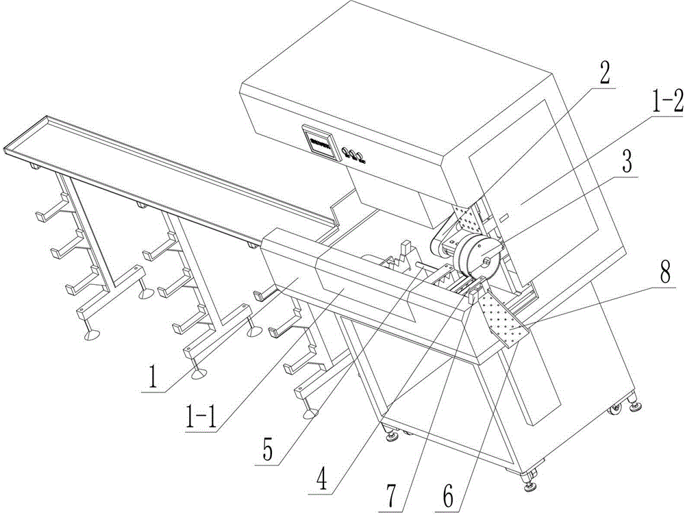
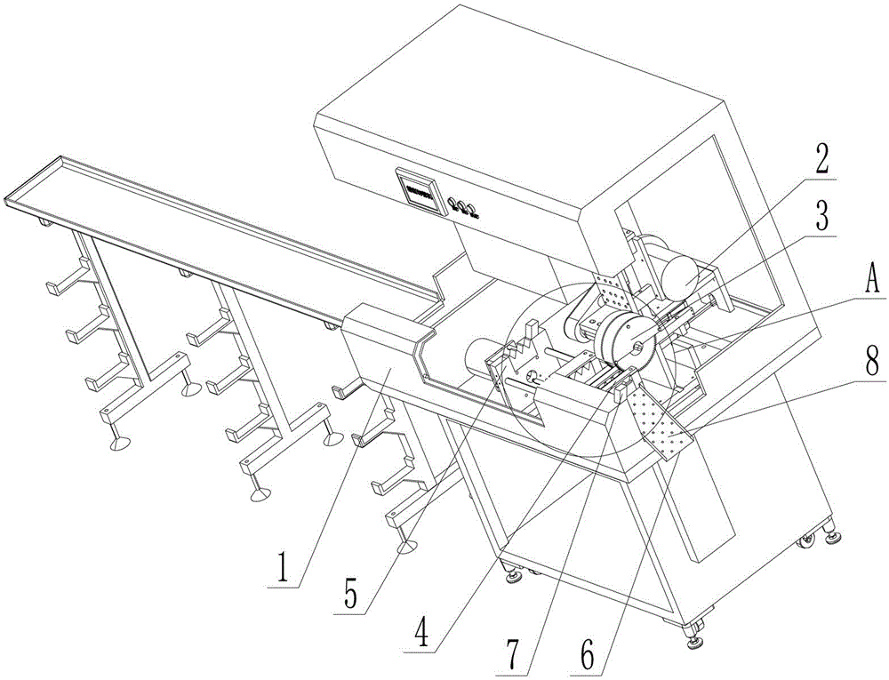
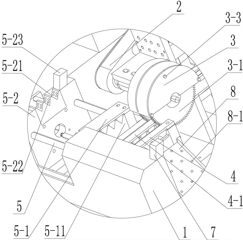
[0023] Such as figure 1 , figure 2 , image 3 , Figure 4 As shown, a fully automatic pipe cutting machine provided by the present invention includes a frame 1, a motor 2, a cutting device 3, a workpiece fixture 4, and a feeding device 5. The motor 2 drives the cutting device 3 for cutting, and the workpiece fixture 4 holds The workpiece is matched with the cutting device 3, and the feeding device 5 carries out forward feeding of the workpiece. The cutting device 3 includes multiple groups of cutters 3-1, and a limit block 3-1 is arranged between adjacent two groups of cutters 3-1. 2. The distance between the two adjacent groups of cutting knives 3-1 separated by the limit stopper 3-2 is consistent with the required length of the workpiece after being processed, and the workpiece fixture 4 includes a plurality of workpiece chucks 4- 1. Th...


PUM


Abstract

The invention provides a full-automatic pipe cutting machine. The full-automatic pipe cutting machine comprises a rack, a motor, a cutting device, a workpiece fixture and a feeding device. The motor drives the cutting device to conduct cutting processing. The workpiece fixture clamps a workpiece and is matched with the cutting device. The feeding device conducts feeding on the workpiece. The cutting device comprises multiple groups of cutters. Limit stops are arranged between two adjacent groups of cutters. The distance separated by the cutters between two adjacent limit stops is same to the distance needed by the workpiece after being processed. The workpiece fixture comprises multiple workpiece chucks. The multiple workpiece chucks are arrayed in parallel. The cutting processing direction of the cutting device is the horizontal direction. The feeding device comprises a hauling portion and a guide portion. Hauling chucks capable of covering up and down are arranged on the hauling portion. The number of the hauling chucks is same to that of the workpiece chucks on the workpiece fixture. Guide sliding grooves are formed in the guide portion. The number of the guide sliding grooves is same to that of the workpiece chucks on the workpiece fixture. The guide sliding grooves, the corresponding guide chucks and the corresponding workpiece chucks are arranged on the same horizontal straight line.

Description

technical field [0001] The invention relates to a fully automatic pipe cutting machine. Background technique [0002] The existing automatic pipe cutting machine includes a frame, a motor, a cutting device, a workpiece fixture, and a feeding device. The motor drives the cutting device to perform cutting. The workpiece fixture clamps the workpiece and cooperates with the cutting device. Feeding, in which the workpiece fixture has only one workpiece chuck, and the motor drives the cutting device to move up and down for cutting. Only one workpiece in the workpiece chuck can be cut at a time, the processing efficiency is low, time-consuming and laborious, and the motor drives the cutting device up and down, empty Too many strokes will also cause waste of energy, and most of the pipes to be processed are long strip structures. During the feeding process of the feeding device, the pipes in the rear section are easy to move and the front section of the cutting part is bent and tilt...

Claims


Application Information

Patent Timeline
IPC IPC(8): B23D21/00B23Q7/00B23Q11/10B23Q17/24B23Q17/09
Inventor 连威金旭辉章学源连婷婷严泽君
Owner 浙江欣兴汇科技有限公司
Why Eureka
Try Eureka