
J type power amplification circuit based on parasitic compensation and radio frequency power amplifier

A power amplifier circuit and parasitic compensation technology, which is applied in the field of radio frequency communication, can solve problems affecting efficiency and linearity indicators, and achieve the effects of improving work efficiency and linearity indicators, reducing tedious work, and reducing energy loss

Inactive Publication Date: 2015-09-30
CHINA COMM MICROELECTRONICS TECH CO LTD +1
View PDF6 Cites 20 Cited by
  • Summary
  • Abstract
  • Description
  • Claims
  • Application Information

AI Technical Summary

Problems solved by technology

[0005] The purpose of the embodiments of the present invention is to provide a class J power amplifier circuit based on parasitic compensation, which aims to solve the problem that the parasitic parameters generated by the transistor package in the existing class J power amplifier circuit affect the impedance matching of the amplifier, thus affecting the efficiency and linearity index The problem

Method used


Image

  • J type power amplification circuit based on parasitic compensation and radio frequency power amplifier
  • J type power amplification circuit based on parasitic compensation and radio frequency power amplifier
  • J type power amplification circuit based on parasitic compensation and radio frequency power amplifier

Examples


Embodiment Construction

[0016] In order to make the object, technical solution and advantages of the present invention clearer, the present invention will be further described in detail below in conjunction with the accompanying drawings and embodiments. It should be understood that the specific embodiments described here are only used to explain the present invention, not to limit the present invention. In addition, the technical features involved in the various embodiments of the present invention described below can be combined with each other as long as they do not constitute a conflict with each other.

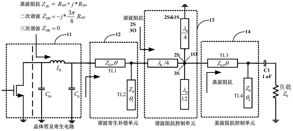
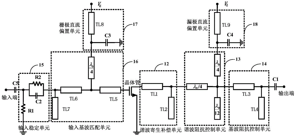
[0017] The embodiment of the present invention uses the harmonic parasitic compensation network to compensate and control the harmonic impedance of the power amplifier transistor, realizes the precise control of the fundamental wave, the second harmonic and the third harmonic impedance, reduces the energy loss of the transistor, and improves the power amplifier High efficiency and linearity, and...


PUM


Abstract

The invention is suitable for the field of radio frequency communication and provides a J type power amplification circuit based on parasitic compensation and a radio frequency power amplifier. The circuit comprises a transistor, a parasitic circuit, a harmonic parasitic compensation unit, a harmonic impedance control unit and a fundamental wave impedance control unit, wherein the input end of the harmonic parasitic compensation unit is connected with the power signal output end of the transistor; the input end of the harmonic impedance control unit is connected with the output end of the harmonic parasitic compensation unit; the input end of the fundamental wave impedance control unit is connected with the output end of the harmonic impedance control unit, and the output end of the fundamental wave impedance control unit is connected with a load through a capacitor. According to the J type power amplification circuit based on parasitic compensation, a harmonic parasitic compensation network is utilized to compensate on harmonic impedance of the transistor of the power amplifier, so that the accurate control of fundamental wave impedance, second harmonic impedance and third harmonic impedance is achieved, the energy loss of the transistor is reduced, the efficiency and linearity of the power amplifier are improved; through independent design of the second harmonic impedance and the third harmonic impedance, each harmonic impedance control circuit does not affect each other, the optimized debugging at a later period is not needed, and the design complexity is reduced.

Description

technical field [0001] The invention belongs to the field of radio frequency communication, and in particular relates to a class J power amplifier circuit and a radio frequency power amplifier based on parasitic compensation. Background technique [0002] Today, the promotion of "green communication" and the increasing scarcity of radio spectrum resources have brought huge challenges to traditional wireless communication systems, resulting in increasingly stringent requirements for efficiency and linearity in communication systems. With the improvement of communication system index requirements, the design index of sub-modules in the communication system is also getting higher and higher, and the radio frequency power amplifier of the final stage of the transmitter in the wireless communication system is the key module that affects the efficiency and linearity of the entire communication system. At the same time, due to the rapid development of the wireless communication ind...

Claims


Application Information

Patent Timeline
Patent Type & Authority Applications(China)
IPC IPC(8): H03F1/02H03F1/32H03F3/20
CPCH03F1/02
Inventor 吴光胜马建国邬海峰成千福朱守奎
Owner CHINA COMM MICROELECTRONICS TECH CO LTD
Learn More