
Video fire-alarm monitoring system and method

A monitoring system and fire alarm technology, which is applied to fire alarms, fire alarms that rely on radiation, and alarms, can solve problems such as damage and loss, and achieve the effects of reducing risks, reducing destructiveness, and reducing casualties

Inactive Publication Date: 2015-09-30
杨明龙
View PDF9 Cites 11 Cited by
  • Summary
  • Abstract
  • Description
  • Claims
  • Application Information

AI Technical Summary

Problems solved by technology

As a result, even equipment and decorations that have not been destroyed by fire or high temperature will be damaged by a large amount of water mist, causing huge losses

Method used


Image

  • Video fire-alarm monitoring system and method
  • Video fire-alarm monitoring system and method
  • Video fire-alarm monitoring system and method

Examples


Embodiment 1

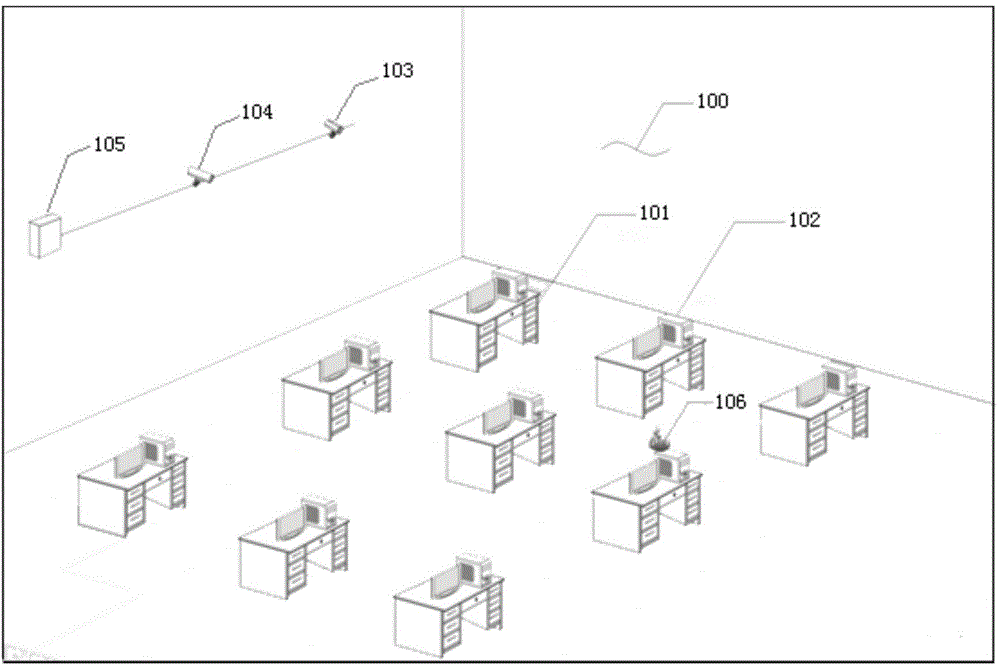
[0076] Take the office as an example, such as figure 1 As shown, a general description is provided for the video fire alarm monitoring system of the present invention (the present invention is not only applicable to offices). The desk 101 is neatly arranged in the office 100, and the computer 102 is placed on the desk 101 according to operation requirements. In order to detect danger more effectively and quickly when a fire alarm occurs, two infrared cameras 103 and 104 with stereo camera function and fire source information with graphics processing function are installed at appropriate positions on one side wall of office 100. Processing device (computer) 105 . For the convenience of monitoring and calculation, the proper location refers to that the cameras 103 and 104 are installed at the same height (the cameras 103 and 104 can be installed on the wall or on the roof), and it is convenient to monitor the position of the entire office 100. If conditions Allowed, the distan...

Embodiment 2

[0078] The difference from Embodiment 1 is that the fire source monitoring device adopts two cameras with both visible light and infrared sensitivity capabilities, and does not have a separate visible light camera.

Embodiment 3

[0080] Such as Figure 12 As shown, if it is used in a crowded space where equipment or materials are closely installed or stacked, such as a warehouse or a machine room, a ceiling infrared camera 107 installed on the roof can be used to cover the entire monitoring area 108 .

[0081] In this space, if the coverage area of ​​one infrared camera is enough to cover the entire monitoring range, the infrared camera should be installed in the center of the roof. If more than one infrared camera is required, an average installation method can be adopted so that each infrared camera covers an equal area. In this embodiment, the visible light camera capability can also be increased by adding a visible light camera or an infrared camera with visible light camera capability, which can be used as a reference for fire alarm monitoring personnel to improve the reliability of the system.


PUM


Abstract

The invention belongs to the field of fire monitoring equipment and specifically relates to a video fire-alarm monitoring system and method. Conventional fire monitoring equipment is triggered only when the flame temperature is near 1000 DEG C or the flame climbs up to several meters high or only when great damage already occurs, which means the best time for firefighting is already missed. The video fire-alarm monitoring system of the invention comprises a fire source monitoring unit and a fire source information processing unit in connection with the fire source monitoring unit. The fire source information processing unit comprises an image recognition module, an artificial intelligence flame identification module, a flame identification database module and a fire source locating module. A suspicious fire source can be rapidly discovered by the infrared remote sensing technique, the fire-alarm level is accurately determined by means of image recognition and artificial intelligence technology, the location of the fire source is precisely calculated, and the corresponding alarm is simultaneously sent to monitoring personnel and the monitoring system, so that the fire can be put out the first time, thereby minimizing the loss.

Description

technical field [0001] The invention belongs to the field of fire monitoring equipment, and in particular relates to a video fire alarm monitoring system and method. Background technique [0002] At present, the monitoring of fire alarms mostly stays in the contact stage. For example: a general temperature sensor must be in contact with the flame to detect the temperature of the flame. Common indoor fire sprinkler triggers fall into this category. Another example: the smoke sensor will not trigger the alarm until the smoke particles reach the detection head of the sensor. [0003] For the aforementioned two types of equipment, since they are usually installed near the roof ceiling, when they detect a fire, the flame may have reached a height of several meters, and the temperature may have reached nearly 1,000 degrees, and the best time to extinguish the fire has already been missed; During this time, a large amount of water mist can only be sprayed to cool down and isolat...

Claims


Application Information

Patent Timeline
Patent Type & Authority Applications(China)
IPC IPC(8): G08B17/12
CPCG08B17/125
Inventor 吴坦肖诗奇
Owner 杨明龙
Learn More