
Touch display screen and manufacturing method thereof and display device

A technology of touch display screen and production method, which is applied in the direction of instruments, electrical digital data processing, input/output process of data processing, etc., and can solve problems such as reducing touch sensitivity, affecting display effect, and blocking primary color units

Active Publication Date: 2015-09-30
ANHUI JINGZHUO OPTICAL DISPLAY TECH CO LTD
View PDF4 Cites 6 Cited by
  • Summary
  • Abstract
  • Description
  • Claims
  • Application Information

AI Technical Summary

Problems solved by technology

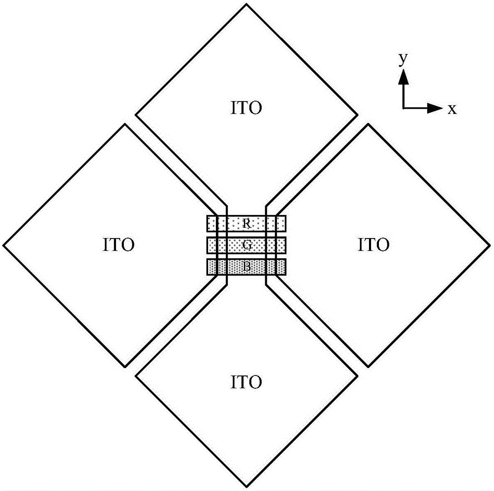
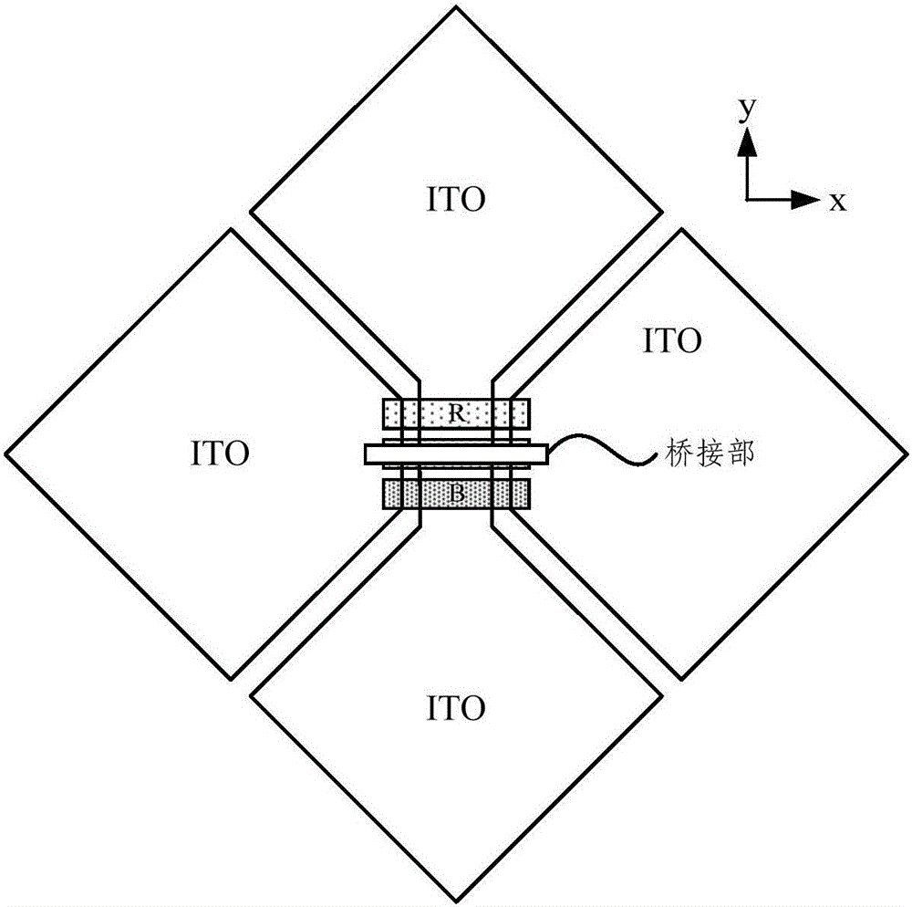
[0003] like figure 2 As shown, a display unit is arranged under the metal layer, and the primary color unit R (red) G (green) B (blue) is parallel to the x direction, as shown in image 3 As shown, in the prior art, a single bridge structure is used to conduct the two electrodes in the x direction, and the bridge part is parallel to the primary color unit, which will cause a large block to a certain primary color unit, and will have a bridging shadow effect , or produce grating interference effect, affecting the display effect
[0004] like Figure 4 As shown, another single-bridge structure adopts an oblique single-bridge scheme, and the bridging part obliquely spans three primary color units. Although it can improve the bridging shadow effect and the grating interference effect, the area facing the bridging part and the electrode in the y direction will increase, resulting in a larger coupling capacitance, and an increase in coupling capacitance will reduce touch sensitivity

Method used


Image

  • Touch display screen and manufacturing method thereof and display device
  • Touch display screen and manufacturing method thereof and display device
  • Touch display screen and manufacturing method thereof and display device

Examples


Embodiment Construction

[0046] In order to understand the above-mentioned purpose, features and advantages of the present invention more clearly, the present invention will be further described in detail below in conjunction with the accompanying drawings and specific embodiments. It should be noted that, in the case of no conflict, the embodiments of the present application and the features in the embodiments can be combined with each other.

[0047] In the following description, many specific details are set forth in order to fully understand the present invention. However, the present invention can also be implemented in other ways different from those described here. Therefore, the protection scope of the present invention is not limited by the specific details disclosed below. EXAMPLE LIMITATIONS.

[0048] like Figure 5 As shown, the touch display screen according to one embodiment of the present invention includes:

[0049] The base (not shown in the figure) can be made of glass,

[0050] a...


PUM


Abstract

The invention relates to a touch display screen and a manufacturing method thereof and a display device. The touch display screen comprises a substrate and a conductive metal layer; the conductive metal layer is disposed on one side of the substrate and comprises a plurality of first electrodes arranged in a first direction and a plurality of second electrodes arranged in a second direction; the first direction is perpendicular to the second direction; every two second electrodes are connected through a first conductive part and a second conductive part, between which a lap joint part insulated to the second electrodes and the first and second conductive parts is provided; the conductive metal layer further comprises first and second bridge parts disposed between two adjacent first electrodes; each first bridge part is electrically connected with one of two first electrodes and the corresponding lap joint part; each second bridge part is electrically connected with the other of two first electrodes and the corresponding lap joint part. The touch display screen according to the technical scheme has the advantages that displaying effect is improved and touch effect is unaffected.

Description

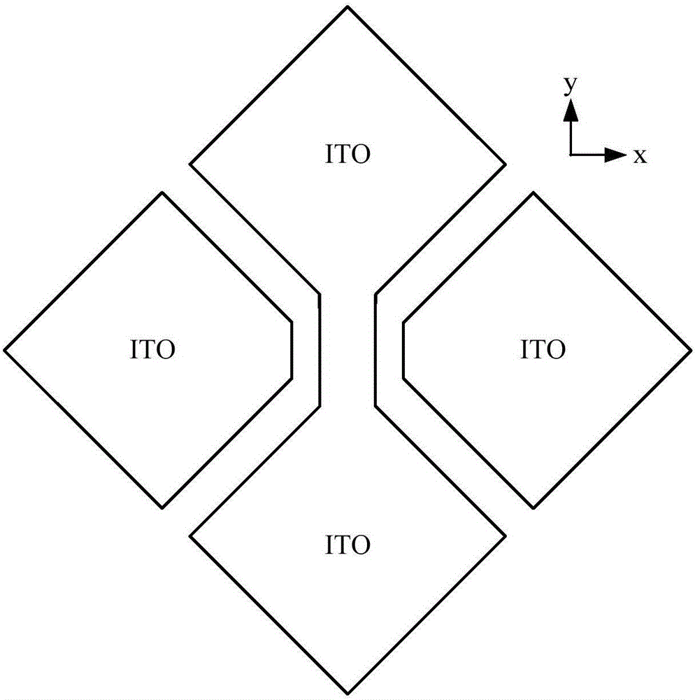
technical field [0001] The present invention relates to the field of display technology, in particular, to a touch display screen, a method for manufacturing a color filter, and a display device. Background technique [0002] In the prior art, the multi-touch design on the on cell display panel generally adopts a metal bridging structure, and the bridging is a single bridge solution. like figure 1 As shown, the metal layer on the touch screen in the prior art generally includes electrodes arranged in the x direction and the y direction (for example, ITO, ie, indium tin oxide is used). [0003] like figure 2 As shown, a display unit is arranged under the metal layer, and the primary color unit R (red) G (green) B (blue) is parallel to the x direction, as shown in image 3 As shown, in the prior art, a single bridge structure is used to conduct the two electrodes in the x direction, and the bridge part is parallel to the primary color unit, which will cause a large block t...

Claims


Application Information

Patent Timeline
IPC IPC(8): G06F3/041G06F3/044
Inventor 夏栋郑刚强
Owner ANHUI JINGZHUO OPTICAL DISPLAY TECH CO LTD
Learn More