A high-pressure combustion chamber cooling jacket inlet and outlet structure and its processing method

A processing method and combustion chamber technology, applied in the aerospace field, can solve the problems of channel structure deformation, large local flow resistance, and difficulty in removing excess burrs, and achieve the effects of improving work performance, ensuring uniformity, and avoiding burrs.

Active Publication Date: 2017-09-26
BEIJING AEROSPACE PROPULSION INST
View PDF5 Cites 0 Cited by
  • Summary
  • Abstract
  • Description
  • Claims
  • Application Information

AI Technical Summary

Problems solved by technology

[0004] Since the high-strength metal on the outer wall at the inlet and outlet of the interlayer channel is completely removed, only the inner wall with lower strength is left, resulting in a decrease in the local pressure bearing capacity at the inlet and outlet of the cooling jacket formed by traditional processing methods, which in turn affects the entire cooling jacket pressure capacity
Moreover, the entrance and exit of the channel of this forming method are limited by the structural strength, and the opening size of the entrance and exit should not be too large, resulting in a large local flow resistance, which may even account for more than half of the flow resistance of the entire cooling channel, seriously affecting the design performance of the entire product
The traditional processing method for the entrance and exit of the channel is intermittent turning, which is prone to deformation of the channel structure and difficult to remove excess burrs, which will affect the performance of the product

Method used


Image

  • A high-pressure combustion chamber cooling jacket inlet and outlet structure and its processing method
  • A high-pressure combustion chamber cooling jacket inlet and outlet structure and its processing method
  • A high-pressure combustion chamber cooling jacket inlet and outlet structure and its processing method

Examples


Embodiment Construction

[0032] The present invention will be described in further detail below in conjunction with the accompanying drawings and specific embodiments.

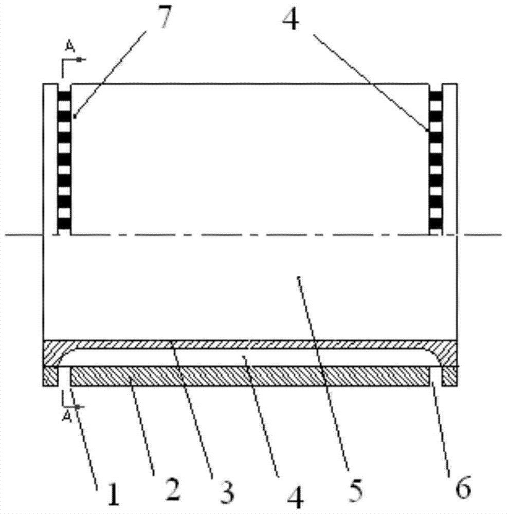
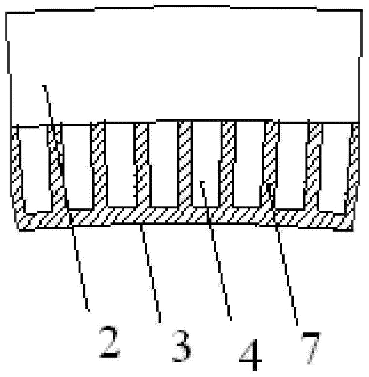
[0033] Such as Figure 5 and Image 6 As shown, the inlet and outlet structure of the cooling jacket of the high-pressure combustor includes a cylindrical combustor inner wall 3 and a combustor outer wall 2 . An interlayer channel 4 is formed between the inner and outer walls, and the space in the combustion inner wall 3 forms a combustion chamber 5 . The connecting ribs 7 are formed by milling grooves on the combustion inner wall 3 . The outer wall of the combustion chamber 2 is connected to the connecting ribs 7 of the inner wall of the combustion chamber 3 by high-strength metal formed by electroforming or diffusion welding, and the gap between the connecting ribs 7 is the interlayer channel 4 .

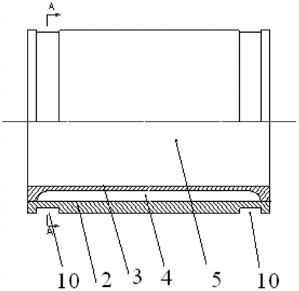
[0034] Different from the prior art, the formation of the interlayer channel inlet 1 and the interlayer channel outlet 6 of the prese...


PUM


Abstract

The invention belongs to the high-temperature and high-pressure thermal protection technology in the field of aerospace, and specifically discloses an inlet and outlet structure of a cooling jacket of a high-pressure combustion chamber and a processing method thereof. The inlet and outlet structure includes the inner wall of the combustion chamber and the outer wall of the combustion chamber. The two ends of the outer wall of the combustion chamber are processed with annular grooves, and the inlet and outlet holes are processed at the bottom. The two ends form the entrance and exit of the interlayer channel. Because the high-strength metal layer is not completely turned off like the prior art, but an annular groove is designed on the outer wall, and the access hole is further processed, and a part or all of the high-strength metal layer is connected with the connecting rib, which strengthens the interlayer channel. Structural strength at the exit. By improving the condition of the weakest link of the pressure vessel, the overall pressure bearing capacity of the thermal protection structure of the combustion device is increased by more than 80%, and the reliability of the burner is improved. In the processing method, EDM and electrolytic processing are used to process the inlet and outlet holes at the bottom of the annular groove, which avoids the burrs produced by intermittent turning and does not damage the connecting ribs.

Description

technical field [0001] The invention belongs to the high-temperature and high-pressure thermal protection technology in the field of aerospace, and in particular relates to an inlet and outlet structure of a cooling jacket of a high-pressure combustion chamber and a processing method thereof. Background technique [0002] Pressure vessel is a relatively common production and living equipment, which is widely used in various fields of people's production and life, such as gas chemical industry, aerospace, metallurgy and various test equipment. Taking aerospace products as an example, it is well known that the rocket engine is the heart of the space vehicle and plays an extremely important role in the entire rocket system, so the requirements for its reliability are very high. The thrust chamber of a rocket engine is a high-pressure, high-temperature container. At present, the thrust chamber of the liquid rocket engine generally adopts the method of regenerative cooling to co...

Claims


Application Information

Patent Timeline
Patent Type & Authority Patents(China)
IPC IPC(8): F23R3/42
Inventor 高翔宇许晓勇孙纪国丁兆波王维彬乔桂玉田原赵世红李丹琳刘红珍王召程鹏王仙
Owner BEIJING AEROSPACE PROPULSION INST
Why Eureka
Try Eureka