
Sewage treatment area for vertical multi-stage ao ecological sewage treatment ponds

A technology for sewage treatment pools and treatment areas, applied in the direction of aerobic and anaerobic process treatment, which can solve the problems of high construction cost and limited sewage treatment capacity, so as to improve efficiency, improve sewage treatment effect, and ensure a stable living environment Effect

Active Publication Date: 2017-03-15
FUJIAN GUANGHUILONG ENVIRONMENTAL PROTECTION TECH
View PDF8 Cites 0 Cited by
  • Summary
  • Abstract
  • Description
  • Claims
  • Application Information

AI Technical Summary

Problems solved by technology

[0004] The invention provides a sewage treatment area for a vertical multi-stage AO ecological sewage treatment pool to overcome the problems of limited sewage treatment capacity or high construction cost of the sewage treatment pools existing in the existing sewage treatment area

Method used


Image

  • Sewage treatment area for vertical multi-stage ao ecological sewage treatment ponds
  • Sewage treatment area for vertical multi-stage ao ecological sewage treatment ponds
  • Sewage treatment area for vertical multi-stage ao ecological sewage treatment ponds

Examples


Embodiment approach 1

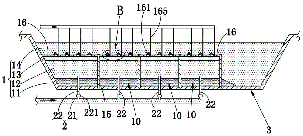
[0021] refer to figure 1 , figure 2 , used in the sewage treatment area of ​​the vertical multi-stage AO ecological sewage treatment pool, the treatment area 1 is composed of a sludge layer 11, an anaerobic layer 12, anoxic layer 13 and an aerobic layer 14 which are stacked sequentially from bottom to top, In the treatment area 1, a plurality of partitions 10 are formed by dividing by criss-cross partitions 15, and the top of the partitions 15 is located at the junction of the aerobic layer 14 and the anoxic layer 13; the top cover of each partition 10 is provided with a ballast Plates 16, each ballast plate 16 is provided with at least three through holes 160, and the through holes 160 are all in the shape of a tapered hole with a large top and a small bottom. The structure setting of the ballast plate 16 creates certain resistance to the sewage flowing upwards, so that the sewage forms convection between the anaerobic layer 12 and the anoxic layer 13, thereby prolonging th...

Embodiment approach 2

[0025] The difference between this embodiment and Embodiment 1 is that: refer to image 3 , Figure 4 , the guide body 161 of the present embodiment is a hollow structure, and the upper cone wall of the guide body 161 is provided with several air outlet holes 167, and the lower cone wall of the guide body 161 is provided with several water holes, or as image 3 , Figure 4 As shown, the water hole 163 is arranged at the bottom of the guide body 161, and the inside of the guide body 161 is equipped with an aerobic filler 164 and / or anoxic filler 164, and the guide body 161 is also equipped with a gas supply pipe for connecting to it. The aeration pipe 165 constitutes an aeration structure. The air blown into the aeration pipe 165 is discharged upwards from the air outlet 167, and the sewage flowing upwards from the anoxic layer 13 can also enter the guide body 161 through the water hole 163, and the sludge entering the guide body 161 can also pass through the water guide body...

Embodiment approach 3

[0027] The difference between this embodiment and Embodiment 1 is that: refer to Figure 5 , Image 6 The aeration structure of this embodiment adopts the conventional aeration device 17 in the prior art, and the aeration device 17 is arranged above each through hole 160, and the aeration device 17 is assembled on the above-mentioned ballast plate 16. In addition, refer to Image 6 , the wall of the through hole 160 is also provided with a helical groove 166, the setting of the helical groove 166 can play a certain diversion effect on the sewage flowing through the through hole 160, so that it forms a certain swirl flow, and further improves the aerobic flow of the sewage. The diffusion rate of layer 14.


PUM


Abstract

The invention relates to a sewage treatment area for a vertical multistage AO ecological sewage treatment tank. The treatment area is composed of a sludge layer, an anaerobic layer, an anoxic layer and an aerobic layer which are successively superimposed from bottom to top. The inside of the treatment area is divided by crisscrossed separator plates into a plurality of septal areas. The tops of the separator plates are positioned at the junction of the aerobic layer and the anoxic layer. The top of each separator plate is covered with a ballast plate. Each ballast plate is provided with at least a through hole. The structure setting of the ballast plates provides a certain resistance for upflowing sewage. Thus, convection current of sewage is formed between the anaerobic layer and the anoxic layer, time for anaerobic degradation of sewage at the anaerobic layer and time for denitrification reaction of sewage at the anoxic layer are prolonged, and anaerobic degradation and denitrification of sewage are more complete. With the arrangement of the through holes in the ballast plates, sewage can be dispersed rapidly so as to raise aerobic degradation and nitration efficiency of an organic matter, reduce load of subsequent sewage treatment processes and enhance the overall sewage treatment efficiency and quality.

Description

technical field [0001] The invention relates to a sewage treatment area of ​​a sewage treatment pool, in particular to a sewage treatment area for a vertical multi-stage AO ecological sewage treatment pool. Background technique [0002] The main structure of the vertical multi-stage AO ecological sewage treatment pool is a pool with a water depth greater than 6 meters. Its main body is composed of sludge stabilization and storage area, anaerobic layer, anoxic layer, aerobic area, plant planting area, etc. vertically (from bottom to top). It is a biological (such as: bacteria, algae, protozoa, metazoans, aquatic plants, higher aquatic animals) and non-biological (light, wind, temperature, organic matter, PH value, dissolved oxygen, N and P nutrients, etc.) part composed of artificial ecosystems. [0003] The top of each partition in the sewage treatment area of ​​the existing vertical multi-stage AO ecological sewage treatment pool is an open structure, and the sewage flowi...

Claims


Application Information

Patent Timeline
Patent Type & Authority Patents(China)
IPC IPC(8): C02F3/30
Inventor 唐宏军
Owner FUJIAN GUANGHUILONG ENVIRONMENTAL PROTECTION TECH
Learn More