
Manufacturing method of MEMS device

A manufacturing method and device technology, applied in the manufacture of microstructure devices, techniques for producing decorative surface effects, decorative art, etc., can solve problems such as device failure and SiGe layer peeling, and achieve the goal of reducing stress and reducing the thickness of the SiGe layer Effect

Active Publication Date: 2015-09-30
SEMICONDUCTOR MANUFACTURING INTERNATIONAL (BEIJING) CORP
View PDF3 Cites 0 Cited by
  • Summary
  • Abstract
  • Description
  • Claims
  • Application Information

AI Technical Summary

Problems solved by technology

[0007] In view of the above-mentioned shortcomings of the prior art, the object of the present invention is to provide a method for manufacturing a MEMS device, which is used to solve the problem in the prior art that the SiGe layer is peeled off due to stress and causes the device to fail when the SiGe layer is formed.

Method used


Image

  • Manufacturing method of MEMS device
  • Manufacturing method of MEMS device
  • Manufacturing method of MEMS device

Examples


Embodiment Construction

[0049] Embodiments of the present invention are described below through specific examples, and those skilled in the art can easily understand other advantages and effects of the present invention from the content disclosed in this specification. The present invention can also be implemented or applied through other different specific implementation modes, and various modifications or changes can be made to the details in this specification based on different viewpoints and applications without departing from the spirit of the present invention.

[0050] see Figure 1 to Figure 10 . It should be noted that the diagrams provided in this embodiment are only schematically illustrating the basic idea of ​​the present invention, and only the components related to the present invention are shown in the diagrams rather than the number, shape and shape of the components in actual implementation. Dimensional drawing, the type, quantity and proportion of each component can be changed ar...


PUM


Abstract

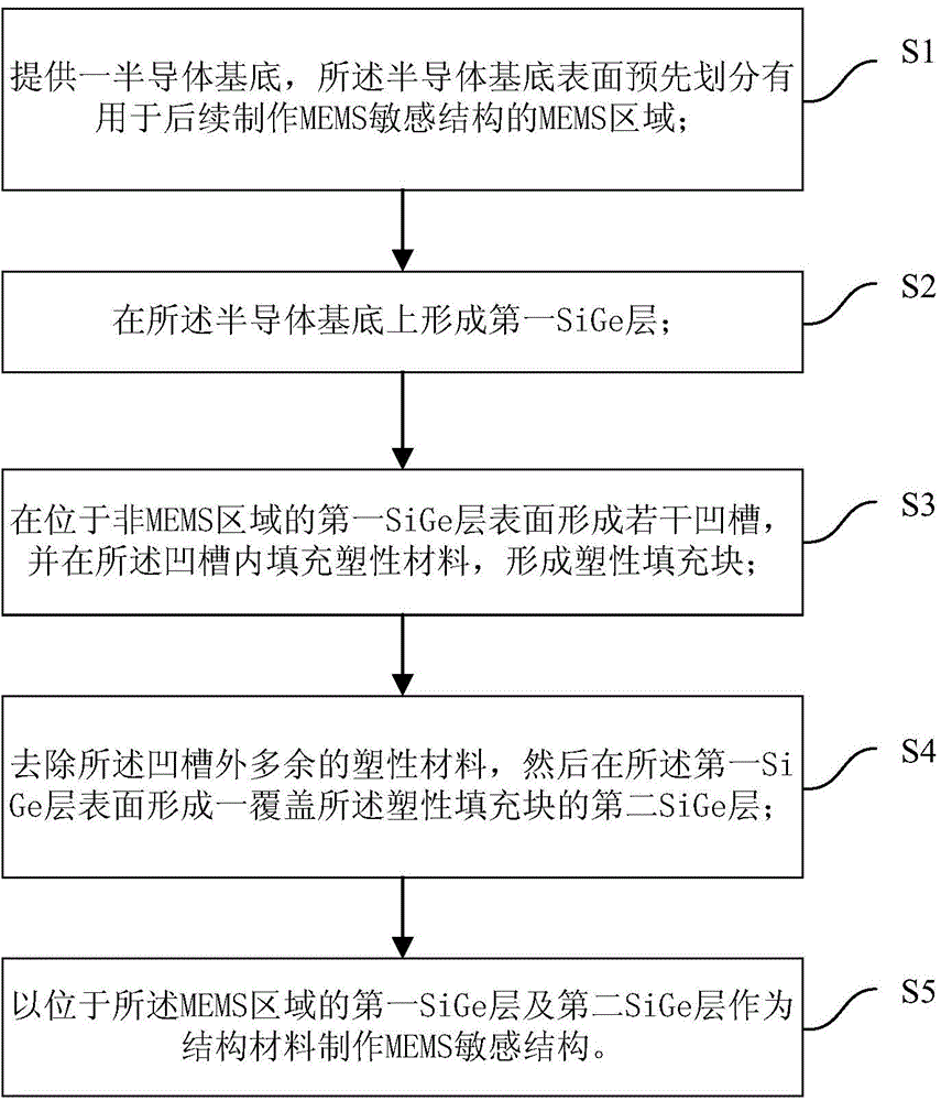
The invention provides a manufacturing method of an MEMS device. The manufacturing method at least comprises the following steps: S1, providing a semiconductor substrate, wherein an MEMS region for the post-production of an MEMS sensitive structure is divided in advance on the surface of the semiconductor substrate; S2, forming a first SiGe layer on the semiconductor substrate; S3, forming a plurality of grooves in the surface of the first SiGe layer positioned on a non-MEMS region, and filling the grooves with a plastic material so as to form a plastic filling block; S4, removing residual plastic materials outside the grooves, and then forming a second SiGe layer covering the plastic filling block on the surface of the first SiGe layer; and S5, manufacturing the MEMS sensitive structure by taking the first SiGe layer and the second SiGe layer, which are positioned on the MEMS region, as structural materials. According to the manufacturing method provided by the invention, the plastic filling block is added into the SiGe layers, and the stress in the plastic filling block is absorbed by utilizing the plastic deformation capacity of the plastic filling block, so that the stripping phenomenon of the SiGe layer is prevented effectively; furthermore, the plastic filling block is positioned in the non-MEMS region, and the functions of the device cannot be affected.

Description

technical field [0001] The invention belongs to the field of semiconductors and relates to a manufacturing method of MEMS devices. Background technique [0002] Micro-Electro-Mechanical System (MEMS, Micro-Electro-Mechanical System) refers to a micro-device or system that can be mass-produced and integrates micro-mechanisms, micro-sensors, micro-actuators, signal processing and control circuits, and interfaces, communications and power supplies. . It is developed on the basis of semiconductor manufacturing technology. MEMS technology uses a series of existing technologies and materials such as lithography, corrosion, and thin film in semiconductor technology. Therefore, from the perspective of manufacturing technology itself, the basic manufacturing technology in MEMS is mature. However, MEMS focuses more on ultra-precision machining, and involves many disciplines such as microelectronics, materials, mechanics, chemistry, and mechanics. There are currently many types of M...

Claims


Application Information

Patent Timeline
Patent Type & Authority Applications(China)
IPC IPC(8): B81C1/00
Inventor 郑超李广宁沈哲敏
Owner SEMICONDUCTOR MANUFACTURING INTERNATIONAL (BEIJING) CORP
Learn More