Discharge plasma vehicle exhaust gas treatment device with rotating spiral electrode and treatment method thereof

A discharge plasma and tail gas treatment technology, which is applied in separation methods, chemical instruments and methods, and dispersed particle separation, can solve problems such as low purification efficiency and uneven plasma, and achieve high purification efficiency, no secondary pollution, Solve the effect of high power consumption

Active Publication Date: 2017-03-01
HARBIN INST OF TECH
View PDF5 Cites 8 Cited by
  • Summary
  • Abstract
  • Description
  • Claims
  • Application Information

AI Technical Summary

Problems solved by technology

[0004] The purpose of the present invention is to solve the problem of uneven plasma generation and low purification efficiency in the existing low-temperature plasma reactor used for automobile exhaust treatment, and to provide a discharge plasma automobile exhaust treatment device with a rotating spiral electrode and its treatment. method

Method used


Image

  • Discharge plasma vehicle exhaust gas treatment device with rotating spiral electrode and treatment method thereof

Examples


specific Embodiment approach 1

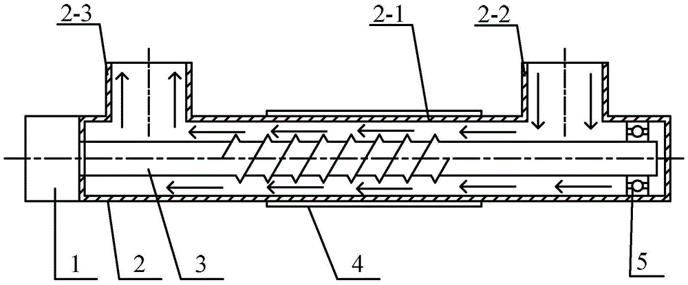
[0019] Specific implementation mode one: the following combination figure 1 Describe this embodiment, the discharge plasma vehicle exhaust treatment device with rotating spiral electrode described in this embodiment, it comprises motor 1, tail gas plasma processing tube 2, spiral electrode 3 and copper tube 4,

[0020] Tail gas plasma treatment tube 2 is composed of horizontal tail gas treatment section 2-1, tail gas inlet section 2-2 and tail gas outlet section 2-3, tail gas inlet section 2-2 is at the head end side of horizontal tail gas treatment section 2-1 It is vertically connected with the horizontal tail gas treatment section 2-1, the tail gas outlet section 2-3 is vertically connected with the horizontal tail gas treatment section 2-1 at the end side of the horizontal tail gas treatment section 2-1, and the tail gas inlet section 2-2 Located on the same side as the tail gas outlet section 2-3 on the same side as the horizontal tail gas treatment section 2-1;

[0021]...

specific Embodiment approach 2

[0023] Specific implementation mode two: the following combination figure 1 Describe this embodiment, this embodiment will further explain the first embodiment, it also includes a positioning bearing 5, the head end of the spiral electrode 3 and the head end of the horizontal tail gas treatment section 2-1 are rotatably connected through the center hole of the positioning bearing 5 .

[0024] The positioning bearing 5 is used for positioning the spiral electrode 3 , and the motor 1 is used for controlling the rotation of the spiral electrode 3 . Positioning bearing 5 is made of non-metallic material.

specific Embodiment approach 3

[0025] Specific implementation mode three: the following combination figure 1 This embodiment will be described. This embodiment will further describe Embodiment 1 or 2. The middle section of the outer surface of the spiral electrode 3 has a dense thread distribution.


PUM


Abstract

The invention relates to a discharge plasma vehicle tail gas treatment apparatus with spiral electrode rotating, and a discharge plasma vehicle tail gas treatment method with spiral electrode rotating, and belongs to the technical field of vehicle tail gas treatment. A purpose of the present invention is to solve problems of non-uniform plasma generation and low purification efficiency of the existing low temperature plasma reactor for the vehicle tail gas treatment. The discharge plasma vehicle tail gas treatment apparatus comprises a motor, a tail gas plasma treatment tube, a spiral electrode and a copper tube, wherein the space between the spiral electrode and the tail gas plasma treatment tube is the vehicle tail gas channel and is the plasma reaction zone, one end of the spiral electrode is connected with the motor, and the other end is fixed at the head end of the horizontal tail gas treatment section. According to the method, the copper tube and the spiral electrode are connected to the power supply, and then the motor drives the spiral electrode to rotate, such that the treatment on the vehicle tail gas is achieved under the effect of the plasma in the horizontal tail gas treatment section. The apparatus and the method of the present invention are used for the vehicle tail gas treatment.

Description

technical field [0001] The invention relates to a discharge plasma automobile tail gas treatment device with a rotating spiral electrode and a treatment method thereof, belonging to the technical field of automobile tail gas treatment. Background technique [0002] As the most important means of modern transportation, the automobile makes people's life more convenient and faster, but it also brings many unavoidable problems. The CO and NO emitted by it x , HC, SO 2 , Pb and other pollutants are not only harmful to human health, but also the main components of acid rain and photochemical smog. Automobile exhaust pollution has attracted widespread attention around the world. According to the survey, more than 90% of CO, more than 60% of HC and more than 30% of NO in urban air x from vehicle emissions. It can be seen that the purification of pollutants in automobile exhaust is a top priority. [0003] In recent years, the rapidly developed low-temperature plasma technology...

Claims


Application Information

Patent Timeline
Patent Type & Authority Patents(China)
IPC IPC(8): B01D53/32
Inventor 唐井峰钱俊杰孟繁星赵辉史晓蕾赵晓璐
Owner HARBIN INST OF TECH
Why Eureka
Try Eureka