Battery cell device with battery cell and limiting circuit and corresponding method

A technology of battery device and current limiting circuit, which is applied to battery circuit device, circuit device, emergency protection circuit device, etc., can solve the problem of insecurity, damage to battery pack 11, inability to limit battery pack battery overcurrent or fault current, etc. problem, to achieve the effect of reducing the risk of burning and simple cost

Active Publication Date: 2015-09-23
ROBERT BOSCH GMBH
View PDF3 Cites 0 Cited by
  • Summary
  • Abstract
  • Description
  • Claims
  • Application Information

AI Technical Summary

Problems solved by technology

[0010] However, these circuits located outside the battery cells are not able to limit overcurrents or fault currents inside the battery cells, for example due to damage to the battery cells 11 or due to short circuits located inside the battery cells.
Therefore, such lithium-ion battery cells 11 are classified as very "unsafe" from the outset in the range of SIL safety level and ASIL safety level (Savety-Leveln)

Method used


Image

  • Battery cell device with battery cell and limiting circuit and corresponding method
  • Battery cell device with battery cell and limiting circuit and corresponding method
  • Battery cell device with battery cell and limiting circuit and corresponding method

Examples


Embodiment Construction

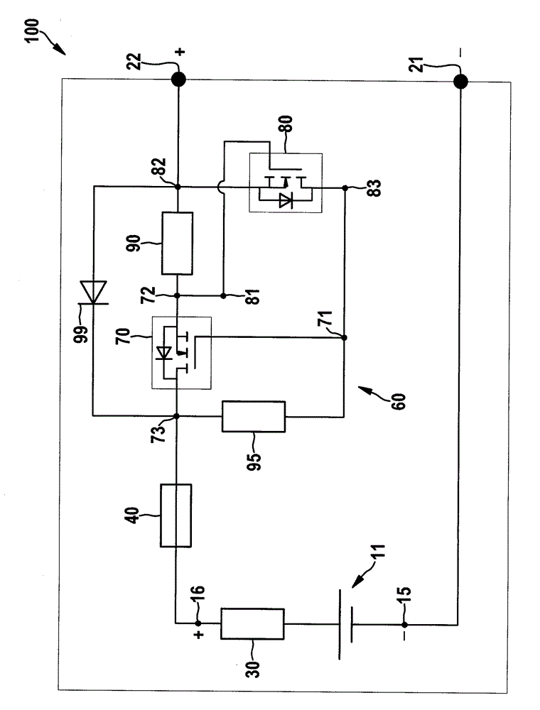
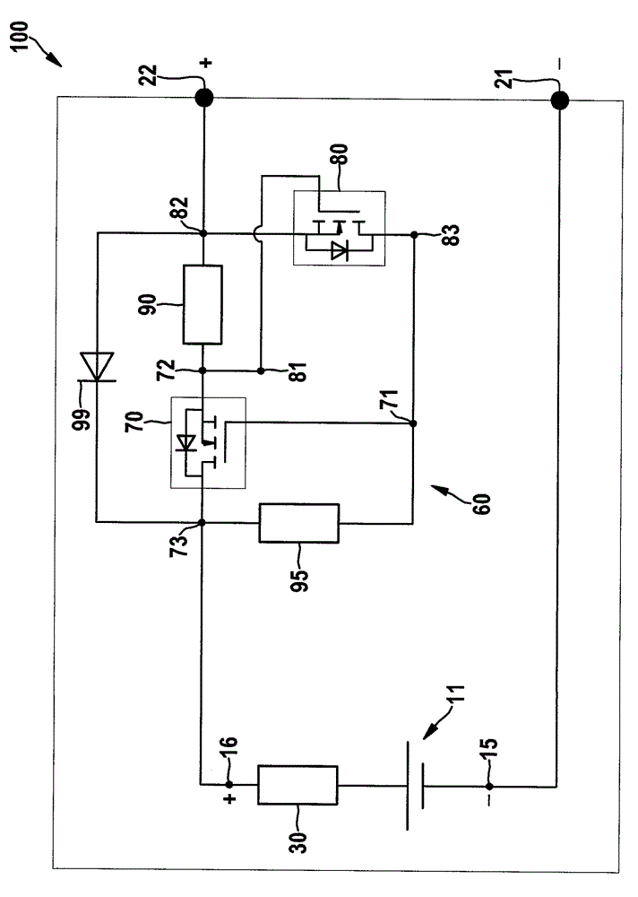
[0047] figure 2 A battery cell device 100 according to a first embodiment of the present invention is shown. The battery cell arrangement 100 includes a lithium-ion battery cell 11 and a current limiting circuit 60 arranged inside the battery cell. The internal resistance of the battery cell 11 is denoted by reference numeral 30 . exist figure 2 Negative battery cell pole 15 and positive battery cell pole 16 are also depicted in . Furthermore, a negative battery cell connection terminal 21 and a positive battery cell connection terminal 22 are also depicted.

[0048] The current limiting circuit 60 is arranged in the current path of the battery cell 11 extending between the positive battery cell pole 16 and the associated positive battery cell connection terminal 22 . The current limiting circuit 60 includes a first transistor 70 which is designed as a field-effect transistor, in particular a power MOSFET. The first transistor 70 has a gate connection 71 , a source conn...


PUM


Abstract

The present invention relates to a battery cell device with a battery cell and a limiting circuit and a corresponding method. The battery cell device is provided with the battery cell connected between two battery cell terminals and the limiting circuit connected between the battery cell and at least one of the two battery cell terminals. The limiting circuit includes a first switching unit which switches a non-conduction state to a conduction state when on a circuit outside the battery cell, and remains the conduction state when there is current lower than a first current value of a current limit value through the battery cell, the battery cell terminals, and the circuit outside the battery cell, and the limiting circuit includes a control unit which switches the first switching unit to the non-conduction state when the value of current through the battery cell, the battery cell terminals, and the circuit outside the battery cell is equal to or exceeds the second current value of the current limit value.

Description

technical field [0001] The invention relates to a battery cell arrangement having a battery cell and a current limiting circuit for limiting the current flowing through the battery cell and the battery cell connection terminals of the battery cell. The invention also relates to a corresponding method for limiting the current flowing through a battery cell and a battery cell connection terminal of the battery cell. Furthermore, the invention relates to a battery management system for a battery system having a battery with a plurality of such battery cell arrangements connected in series. Background technique [0002] Electromobility is playing an increasingly important role in current and future vehicle generations. In this case, the electric drive can either be used entirely as an alternative to the known internal combustion engine or it can be used to assist the internal combustion engine in a hybrid drive. [0003] In electric or hybrid drives, a traction battery is used...

Claims


Application Information

Patent Timeline
IPC IPC(8): H02J7/00H01M50/583
CPCH01M10/425H01M10/441H02H7/18H01M2220/20Y02E60/10H01M50/583
Inventor U.劳舍尔
Owner ROBERT BOSCH GMBH
Why Eureka
Try Eureka