Circuit arrangement for an mrt system, mrt system and method for operating an mrt system

A circuit device and equipment technology, applied in the direction of measuring devices, applications, electrical components, etc., can solve the problems of redundant design, manufacturing and cost consumption, and achieve the effect of simple cost and suitable modification feasibility

Active Publication Date: 2019-05-17
SIEMENS HEALTHCARE GMBH
View PDF7 Cites 1 Cited by
  • Summary
  • Abstract
  • Description
  • Claims
  • Application Information

AI Technical Summary

Problems solved by technology

This can lead, for example, to completely redundant design of certain functions with great component, production and cost outlays.

Method used


Image

  • Circuit arrangement for an mrt system, mrt system and method for operating an mrt system
  • Circuit arrangement for an mrt system, mrt system and method for operating an mrt system
  • Circuit arrangement for an mrt system, mrt system and method for operating an mrt system

Examples


Embodiment Construction

[0061] The examples set forth below are preferred embodiments of the invention. In the exemplary embodiments, the described components of the embodiment are each individual features of the invention which can be considered independently of each other, which also respectively improve the invention independently of each other, and thus also individually or in combination with the illustrated Combinations of different combinations are considered to be part of the invention. Furthermore, the described embodiments can also be supplemented by other features of the invention which have already been described.

[0062] In the figures, elements that are identical, have the same function or correspond to one another are provided with the same reference symbols.

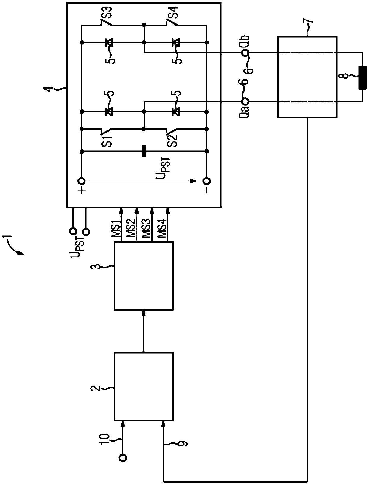
[0063] figure 1 A schematic diagram of a first gradient amplifier 1 is shown, as it can be used, for example, in an MRT system. The first gradient amplifier 1 here comprises a controller or regulating device 2 , a modulator ...


PUM


Abstract

A circuit arrangement for an MRT system, an MRT system with the circuit arrangement and a method for operating an MRT system are disclosed. The circuit arrangement includes a gradient amplifier havinga switch-mode output stage, a regulator device, and a modulator connected therebetween in the circuit. To ensure patient safety, a control path is integrated into a drive path of the circuit arrangement or the MRT system provided for driving a gradient coil, the gradient coil being connected to an output of the switch-mode output stage. The control path includes a limiter stage connected downstream of the regulator device, the modulator, the switch-mode output stage and its supply voltage. The limiter stage is connected in the circuit between the regulator device and an input of the modulator, to limit a control signal output by the regulator device and limit the voltage for the gradient coil provided by the switch-mode output stage at its output.

Description

technical field [0001] The invention relates to a circuit arrangement for an MRT system, an MRT system having such a circuit arrangement and a method for operating such an MRT system. Background technique [0002] Today, in magnetic resonance tomography (MRT) or magnetic resonance imaging, high voltages, field strengths and gradients, ie spatial variations, in particular of the magnetic flux density B, and rapid temporal variations, ie variation rates, are used. At the same time, implants, in particular implants with metal parts, are increasingly used. For the examination of patients with implants, in particular active implants, eg cardiac pacemakers, defibrillators or neurostimulators, in magnetic resonance imaging, ie in an MRT system, on the one hand the implant The implant must be suitable for this examination, ie suitable for use in an MRT device, and on the other hand the MRT device must not lead to a situation where the patient, the implant or the function of the imp...

Claims


Application Information

Patent Timeline
IPC IPC(8): G01R33/385G01R33/36A61B5/055
CPCG01R33/3852G01R33/288G01R33/543H03F3/217H03F2200/129H03F2200/301H03F2200/312H03F2200/351H03F2200/462
Inventor 赫尔穆特·伦兹马赛厄斯·格布哈特迪尔克·施奈德班格尔罗兰德·维尔纳
Owner SIEMENS HEALTHCARE GMBH
Why Eureka
Try Eureka