
Dynamic section control method based on power flow transfer ratio

A technology of power flow transfer and control method, which is applied in the direction of AC network circuits, instruments, electrical components, etc., and can solve problems such as small amount of calculation, impractical cross-section selection, complicated process of selecting power transmission cross-sections, etc.

Active Publication Date: 2015-09-23
POWER DISPATCHING CONTROL CENT OF GUANGDONG POWER GRID CO LTD
View PDF4 Cites 16 Cited by
  • Summary
  • Abstract
  • Description
  • Claims
  • Application Information

AI Technical Summary

Problems solved by technology

[0007] Based on this, it is necessary to solve the problems that the process of selecting the transmission section of the existing power grid is complicated, the selected section is not practical, and the section control is unreasonable. dynamic section control method based on power flow transfer ratio, accurate results, small amount of calculation, convenient and practical

Method used


Image

  • Dynamic section control method based on power flow transfer ratio
  • Dynamic section control method based on power flow transfer ratio
  • Dynamic section control method based on power flow transfer ratio

Examples


Embodiment Construction

[0056] In order to make the purpose, technical solution and advantages of the present invention clearer, the present invention will be further described in detail with reference to the accompanying drawings by taking a large provincial power grid as an example. It should be understood that the specific embodiments described here are only used to explain the present invention, not to limit the present invention.

[0057] A dynamic section control method based on the power flow transfer ratio of the present invention comprises the following steps:

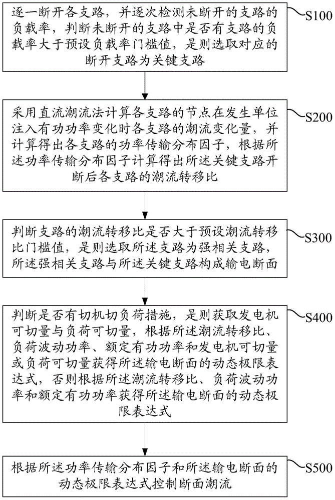
[0058] Step S100, disconnect each branch one by one, and check the load rate of the undisconnected branch one by one, and judge whether there is any branch in the undisconnected branch whose load rate is greater than the preset load rate threshold, and if so, select the corresponding The disconnected branch of is the critical branch.

[0059] In one embodiment, the specific implementation method of selecting the key branch is: using...


PUM


Abstract

The invention relates to a dynamic section control method based on a power flow transfer ratio. The method comprises the following steps: switching off each branch one by one, detecting the load rates of branches which are not switched off gradually, judging whether or not the load rates of certain branches in the branches which are not switched off are greater than a preset load rate threshold value, and if so, selecting corresponding switch-off branches as key branches; calculating the power flow transfer ratio of each branch with a direct-current power flow algorithm; judging whether or not the power flow transfer ratios of the branches are greater than a preset power flow transfer ratio threshold value, if so, selecting the branches for serving as strong correlation branches, wherein the strong correlation branches and the key branches construct a power transmission section; acquiring a dynamic ultimate expression of the power transmission section according to the power flow transfer ratios, load fluctuating power, rated active power and a generator switchable amount or a load switchable amount; and controlling section power flow according to a power transmission distribution factor and the dynamic ultimate expression of the power transmission section. The dynamic section control method is suitable for the complex change of a power grid running way, accurate in results, small in calculation amount, convenient and practical.

Description

technical field [0001] The invention relates to the field of power system operation analysis and control, in particular to a dynamic section control method based on power flow transfer ratio. Background technique [0002] Due to the uneven distribution of energy resources and economic development in various countries and regions in the world, there are large differences in energy composition, price, and load demand. A large amount of electricity needs to be transmitted over long distances through the interconnected grid. In a market-oriented large-scale interconnected power system, the inter-regional economic benefits and increasing load demand make the inter-regional cross-section transmission power closer and closer to its limit value, which gradually threatens the safety and reliability of the system. Therefore, the operation and control of the transmission section has become the focus and difficulty of the daily work of the dispatching department. [0003] Transmission ...

Claims


Application Information

Patent Timeline
Patent Type & Authority Applications(China)
IPC IPC(8): H02J3/00G06Q50/06
Inventor 易杨杨银国罗钢钱峰谭伟徐春华吴国炳陈睿段秦刚杨文佳
Owner POWER DISPATCHING CONTROL CENT OF GUANGDONG POWER GRID CO LTD
Learn More