A fence synchronization method and device
A fence synchronization and fence technology, applied in the field of communication, can solve the problem of chip processing performance degradation
- Summary
- Abstract
- Description
- Claims
- Application Information
AI Technical Summary
Problems solved by technology
Method used
Image
Examples
Embodiment 1
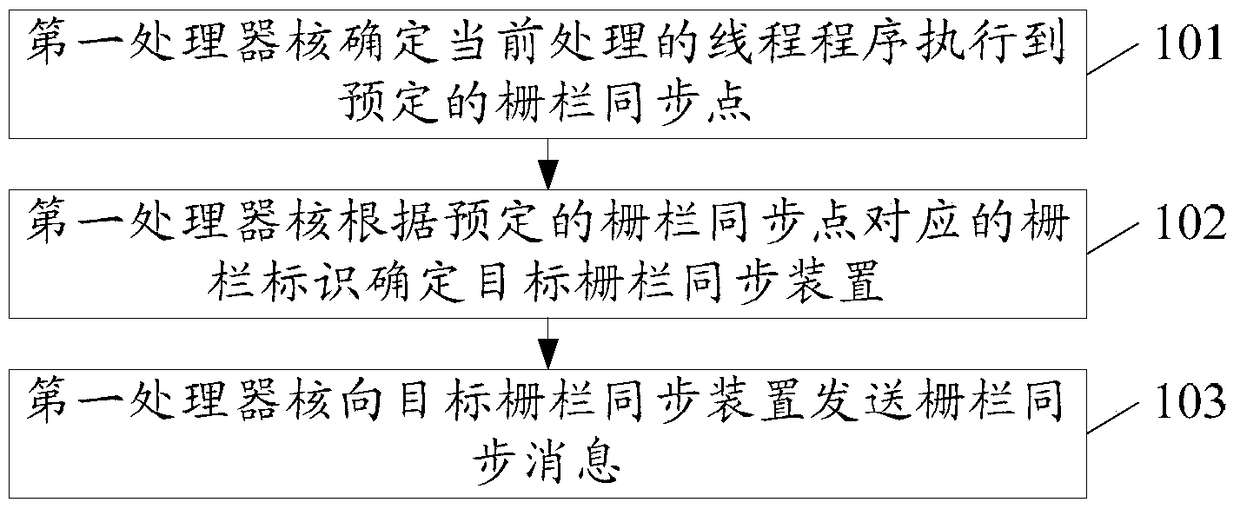
[0095] Embodiment 1 of the present invention provides a barrier synchronization method, which is applied to a chip with a multi-core or many-core processor, and at least two barrier synchronization devices are provided on the chip, such as figure 1 As shown, the method may include:
[0096] 101. The first processor core determines that a currently processed thread program is executed to a predetermined barrier synchronization point. Wherein, the first processor core is any one of all processor cores included in the chip.
[0097] 102. The first processor core determines a target barrier synchronization device according to a barrier identifier corresponding to a predetermined barrier synchronization point.
[0098] Wherein, the fence synchronization method of the embodiment of the present invention is applied to a chip with a multi-core or many-core processor, and at least two fence synchronization devices are arranged on the chip, when any processor core in all processor core...
Embodiment 2
[0104] Embodiment 2 of the present invention provides a barrier synchronization method, which is applied to a chip with a multi-core or many-core processor, and at least two barrier synchronization devices are arranged on the chip, such as figure 2 As shown, the method may include:
[0105] 201. The target barrier synchronization device receives a barrier synchronization message sent by the first processor core.
[0106] Wherein, the barrier synchronization message is sent by the first processor core when it is determined that the currently processed thread program executes to a predetermined barrier synchronization point, the first processor core is any one of all processor cores contained in the chip, and the barrier synchronization message contains the fence identifier corresponding to the fence synchronization point and the number of thread programs participating in the synchronization, and the target fence synchronization device is a fence synchronization device for proc...
Embodiment 3
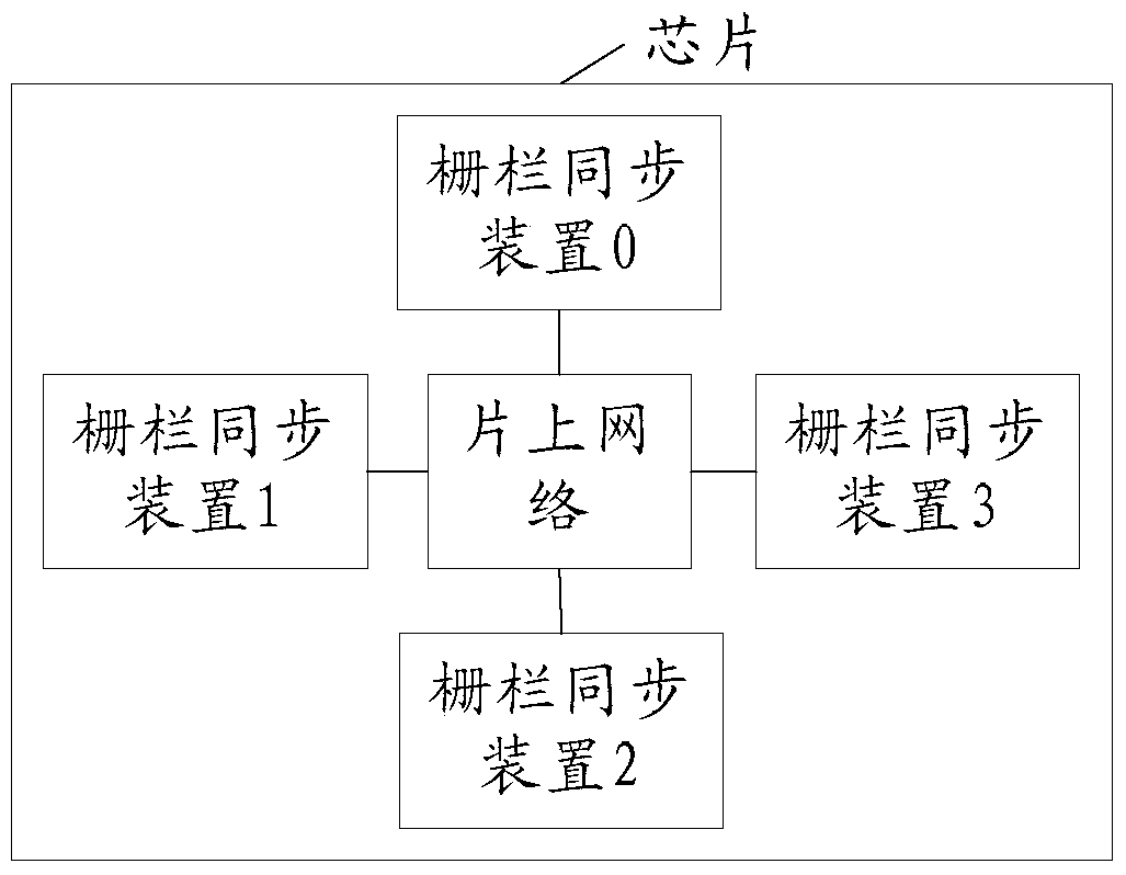
[0113] Embodiment 3 of the present invention provides a barrier synchronization method, which is applied to a chip with a multi-core or many-core processor. At least two barrier synchronization devices are provided on the chip, and the at least two barrier synchronization devices are distributed in the network on chip. different locations, for example image 3 The shown embodiment of the present invention provides a schematic structural diagram of a chip provided with four barrier synchronization devices and has a multi-core or many-core processor. Such as Figure 4 As shown, the barrier synchronization method provided in the embodiment of the present invention may include:
[0114] 301. The first processor core determines that a currently processed thread program is executed to a predetermined fence synchronization point.
[0115] Wherein, the first processor core is any one of all processor cores included in the chip.
[0116] 302. The first processor core determines a ta...
PUM
 Abstract
Description
Claims
Application Information
 - R&D
- Intellectual Property
- Life Sciences
- Materials
- Tech Scout
- Unparalleled Data Quality
- Higher Quality Content
- 60% Fewer Hallucinations
Browse by: Latest US Patents, China's latest patents, Technical Efficacy Thesaurus, Application Domain, Technology Topic, Popular Technical Reports.
© 2025 PatSnap. All rights reserved.Legal|Privacy policy|Modern Slavery Act Transparency Statement|Sitemap|About US| Contact US: help@patsnap.com


