
Oil gas type load reduction pneumatic actuator cylinder and load reduction method thereof

An oil-pneumatic and actuator technology, which is applied to fluid pressure actuators, servo motors, chassis, etc., can solve problems such as increased product weight, blockage, and large buffer pressure

Inactive Publication Date: 2015-09-23
LANDING GEAR ADVANCED MFG
View PDF4 Cites 10 Cited by
  • Summary
  • Abstract
  • Description
  • Claims
  • Application Information

AI Technical Summary

Problems solved by technology

This damping form is easy to cause blockage because the hole is relatively small. On the other hand, when the piston rod moves to the buffer area, the speed change is relatively large, which causes a large buffer pressure in the damping chamber, and the parts are heavily loaded. In order to meet the strength requirements, it must be Strengthen the structural size of the parts in the buffer area, increasing the product weight

Method used


Image

  • Oil gas type load reduction pneumatic actuator cylinder and load reduction method thereof
  • Oil gas type load reduction pneumatic actuator cylinder and load reduction method thereof
  • Oil gas type load reduction pneumatic actuator cylinder and load reduction method thereof

Examples


Embodiment Construction

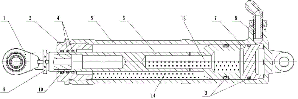
[0024] An oil-pneumatic degradable pneumatic cylinder, such as figure 1 As shown, it is mainly composed of an outer cylinder 5, a piston rod 6, a floating piston 7, an earring joint 1, an end cover 2, a sealing ring, a pipe joint and the like. The floating piston is installed between the closed end of the outer cylinder 5 and the fixed piston 11 of the piston rod 6; the end cover 2 is connected with the outer cylinder 5 through threads, and the end cover 2 and the The fixed piston 11 forms a closed chamber composed of a rod chamber 14 and a rodless chamber 13; the closed chamber is filled with hydraulic oil, and the total amount of hydraulic oil is the closed chamber in this state when the piston rod is fully extended. .

[0025] In order for the piston rod of the actuator to become a differential actuator at the end of the actuator, a certain volume of hydraulic oil is filled between the floating piston 7 and the end cover; the amount of hydraulic oil depends on the position...


PUM


Abstract

The invention discloses an oil gas type load reduction pneumatic actuator cylinder and a load reduction method thereof. The actuator cylinder comprises an outer cylinder, an end cover fixed at one end of the outer cylinder, and a fixed piston arranged in the outer cylinder and mounted on a piston rod, wherein the piston rod partially extends outside the end cover; the other end of the outer cylinder is a closed end provided with a pressure gas joint; a floating piston capable of moving in the length direction of the outer cylinder is arranged between the closed end of the outer cylinder and the fixed piston; a pressure gas cavity is formed between the floating piston and the closed end of the outer cylinder; a rodless cavity is formed between the floating piston and the fixed piston; a rod cavity is formed between the fixed piston and the end cover; and the rodless cavity and the rod cavity are communicated to form a differential structure. The actuator cylinder realizes the supply of needed high load in normal working travel, and reduces the load at the travel terminal to reduce the terminal load impact.

Description

technical field [0001] The invention relates to an oil-gas type load-reducible pneumatic cylinder and a load-reduction method thereof. Background technique [0002] In recent years, due to the characteristics of fast speed, wide application environment and no casualties, UAVs have become more and more widely used. As an important functional structural part of the UAV landing gear, there are currently two main forms of power sources: electric retractable cylinder and pneumatic cylinder. Electric actuators have high requirements on motors, heavy weight, and slow retraction time. For drones that land at high speeds, have requirements for landing gear lowering time and aircraft weight, electric actuators cannot meet their requirements. Pneumatic actuators use high-pressure air as the power source, but the high-pressure gas has a large impact on the movement of the actuator, and the load at the end of the actuator will directly affect the performance of the landing gear and the ...

Claims


Application Information

Patent Timeline
Patent Type & Authority Applications(China)
IPC IPC(8): F15B15/17F15B15/20F15B11/072
CPCF15B15/17B64C25/22F15B15/20
Inventor 陈和潮金军冯广莫超金汪赵宏张威慕建全吴林陈永卿游小红熊过
Owner LANDING GEAR ADVANCED MFG
Learn More