
A crystal oscillator circuit

A technology of crystal oscillation and circuit, which is applied in the direction of electrical components, generator start-up, power automatic control, etc. It can solve the problems of intermittent vibration stop, large output load of crystal oscillation circuit, poor waveform of crystal oscillation circuit, etc., to ensure The effects of stable work, increased excitation power, and reduced capacitive reactance

Active Publication Date: 2015-09-23
BEIJING INST OF SPACECRAFT SYST ENG
View PDF4 Cites 0 Cited by
  • Summary
  • Abstract
  • Description
  • Claims
  • Application Information

AI Technical Summary

Problems solved by technology

[0004] (1) The capacitance value connected in series with the crystal is too small, resulting in insufficient excitation power of the crystal, so that the crystal does not vibrate or stops vibrating intermittently after starting to vibrate;
[0005] (2) The output load of the crystal oscillator circuit is relatively large, and the load capacity is not strong
[0006] (3) The DC voltage at the base of the triode will affect the stability of the crystal oscillator circuit
[0007] (4) The waveform of the crystal oscillator circuit is poor, and the selection of the static operating point of the crystal oscillator circuit is not appropriate

Method used


Image

  • A crystal oscillator circuit

Examples


Embodiment Construction

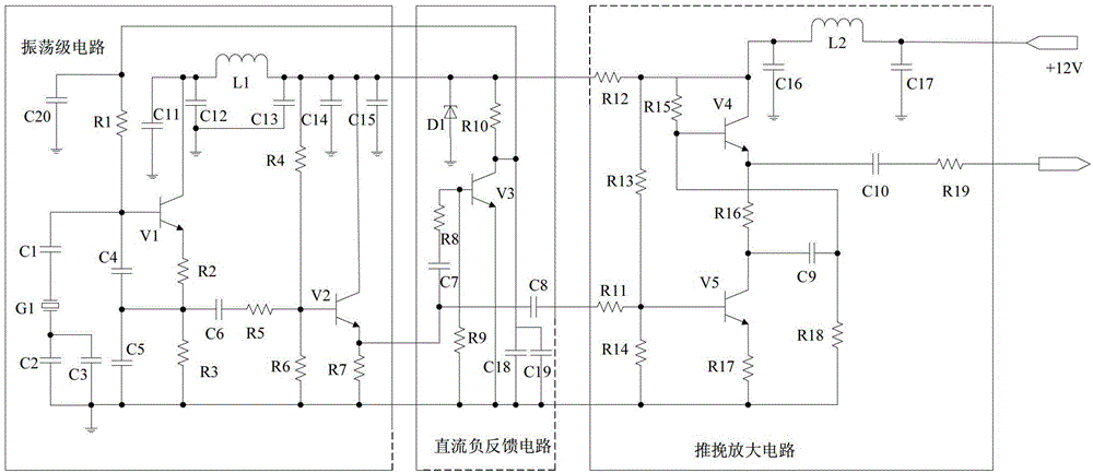
[0020] Such as figure 1 As shown, the crystal oscillating circuit of the present invention includes an oscillating stage circuit, a DC negative feedback circuit, and a push-pull amplifier circuit. The oscillation stage circuit generates an oscillation signal close to the natural frequency of the crystal, and the DC negative feedback circuit uses the DC negative feedback control signal to control the amplitude of the oscillation signal of the oscillation stage circuit, stabilizing the static operating point of the oscillation stage circuit, and the oscillation stage circuit controls the amplitude. The oscillation signal is output to the DC negative feedback circuit, and the DC negative feedback circuit outputs the amplitude-controlled oscillation signal to the push-pull amplifier circuit. The push-pull amplifier circuit is a post-stage amplifier circuit, which amplifies the oscillation signal output by the DC negative feedback circuit. output to the outside.

[0021]The oscill...


PUM


Abstract

The invention relates to a crystal oscillating circuit, which comprises an oscillating stage circuit, a direct current negative feedback circuit, and a push-pull amplifier circuit. The oscillating stage circuit generates an oscillator signal and outputs the oscillator signal to the direct current negative feedback circuit; the direct current negative feedback circuit performs amplitude control on the oscillator signal of the oscillating stage circuit and feeds back the oscillator signal to the oscillating stage circuit; the oscillating stage circuit outputs the oscillator signal which is subjected to the amplitude control to the push-pull amplifier circuit by the direct current negative feedback circuit; and the push-pull amplifier circuit is a post-stage amplifying circuit, amplifies the oscillator signal which is input and subjected to the amplitude control and outputs the oscillator signal to the outside. According to the invention, a transistor V5 adopts an emitter follower, so that an output load of the crystal oscillating circuit is less, and oscillation starting of the crystal is facilitated; and the capacitance of a capacitor which is connected in series with the crystal is increased, so that the capacitive reactance of the capacitor in the circuit is reduced, an alternating current which runs through the crystal is increased, and the driving power of the crystal is increased.

Description

technical field [0001] The invention relates to a crystal oscillation circuit. Background technique [0002] Crystal oscillation circuit is an important part of various electronic equipment circuits. The design of its crystal excitation power has a great influence on the reliability of the equipment. Since the selection of crystal excitation power involves many parameters, the selection of different parameters has great influence on the existing If the crystal oscillator circuit is not properly designed, the crystal excitation power will be insufficient or too large, which cannot meet the conditions for the crystal to start oscillating, so that the crystal will not oscillate or stop oscillating intermittently. [0003] The existing capacitive three-point crystal oscillator circuit has the following deficiencies in design: [0004] (1) The capacitance value connected in series with the crystal is too small, resulting in insufficient excitation power of the crystal, so that t...

Claims


Application Information

Patent Timeline
Patent Type & Authority Patents(China)
IPC IPC(8): H03L3/00H03L5/02H03F3/26
Inventor 王万斌韦欣荣舒卫平曹锦李鸿斌张宏杰
Owner BEIJING INST OF SPACECRAFT SYST ENG
Learn More