Eureka AIR delivers breakthrough ideas for toughest innovation challenges, trusted by R&D personnel around the world.

Piston oil returning device and method

A piston and oil return hole technology, applied to pistons, engine components, machines/engines, etc., can solve problems such as less oil, increased engine oil consumption, and worsened emissions, so as to increase oil return efficiency, improve oil return volume, The effect of reducing oil consumption

Active Publication Date: 2015-09-23
BEIJING INSTITUTE OF TECHNOLOGYGY
View PDF5 Cites 0 Cited by
  • Summary
  • Abstract
  • Description
  • Claims
  • Application Information

AI Technical Summary

Problems solved by technology

However, since the piston is arranged horizontally, the oil scraped off by the piston oil ring and gas ring must flow to the lower half of the piston oil ring groove and nose bridge area along the oil ring groove and ring nose bridge area under the action of gravity, resulting in , the lower half of the piston oil groove and nose bridge area has more oil, and the upper half has less oil, and the evenly distributed oil return holes cannot well adapt to the oil return flow of different amounts of oil
[0004] Because the cylinder and piston are placed horizontally, compared with traditional engines, the oil used to lubricate and cool the piston cannot flow back to the oil pan in time under its own gravity. At the same time, the piston repeatedly passes through the inlet and outlet on the cylinder during work. The air port causes the piston ring to continuously pump oil into the cylinder and the intake and exhaust chambers, resulting in increased oil consumption and worsened emissions of opposed-piston two-stroke engines, which restricts the widespread use of this type of engine

Method used


Image

  • Piston oil returning device and method
  • Piston oil returning device and method
  • Piston oil returning device and method

Examples


Embodiment Construction

[0027] Specific embodiments of the present invention will be described in detail below in conjunction with the accompanying drawings. However, the embodiments of the present invention are not limited thereto.

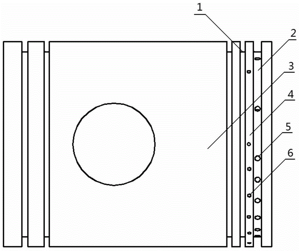
[0028] figure 1 It is a schematic structural diagram of a piston with an oil return hole in an embodiment of the present invention. Such as figure 1 As shown, the piston oil return device suitable for an opposed-piston two-stroke engine includes an oil ring groove 2, and a plurality of oil return holes 5 are arranged at the bottom of the oil ring groove 2; The ring groove 1, the nose bridge area 4 between the last gas ring ring groove 1 and the oil ring ring groove 2, a plurality of oil return holes 6 are arranged on the outer circumference of the nose bridge area 4.

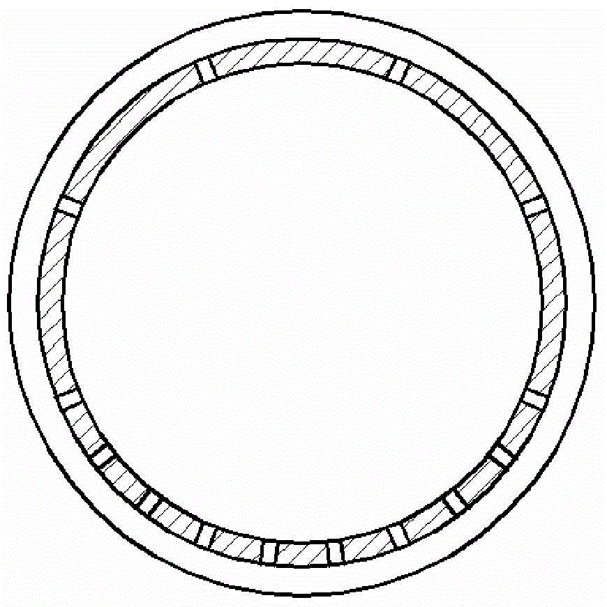
[0029] figure 2 It is a distribution structure diagram of the oil return holes at the bottom of the oil ring groove in the embodiment of the present invention. Such as figure 2 As shown, the oil r...


PUM


Abstract

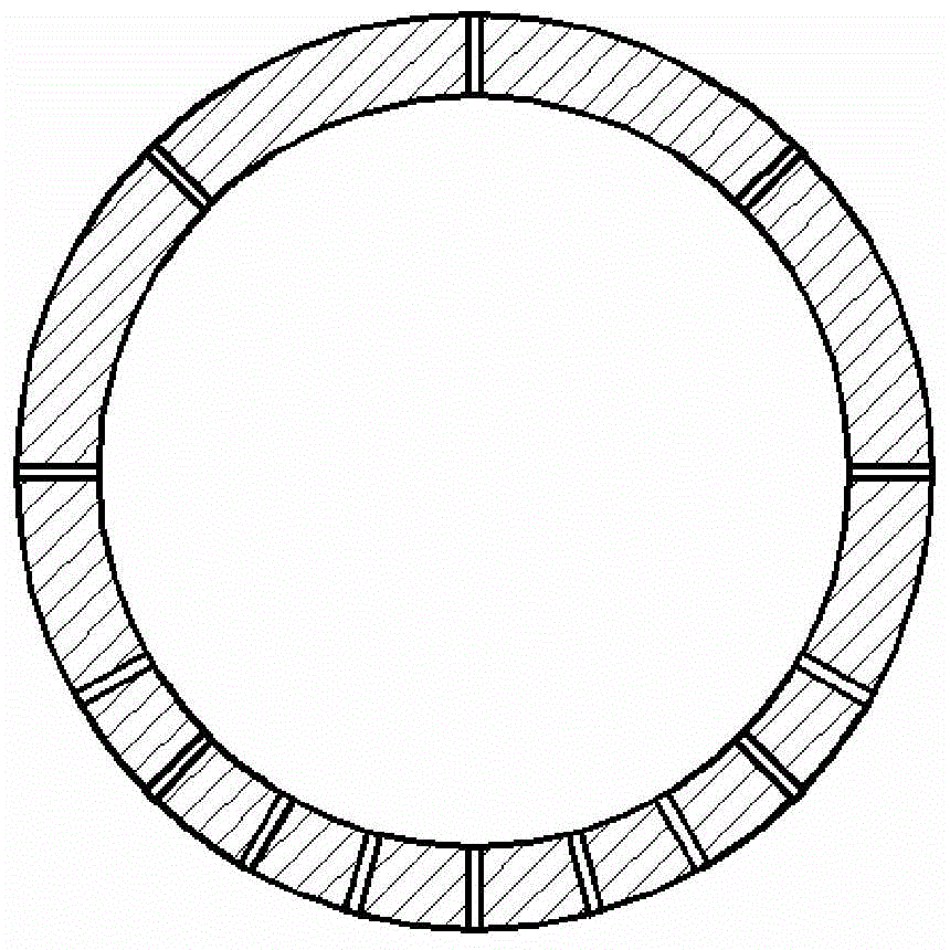
The invention discloses a piston oil returning device and method applicable to an opposed piston two-stroke engine. One or more oil returning channels are arranged at the bottom of an oil ring groove of a piston skirt unequally. The number of the oil returning channels arranged on the upper semi-circle portion of the bottom of the oil ring groove is smaller than that of the oil returning channels arranged on the lower semi-circle portion of the bottom of the oil ring groove. Engine oil at the bottom of the oil ring groove flows back to an engine oil shell through the oil returning channels at the bottom of the oil ring groove. According to the technical scheme, the effective area of the engine oil returning channels on the lower semi-circle portion of a piston is greatly increased, and the piston oil returning device well adapts to the situation that engine oil of the lower half portion of the piston of the opposed piston engine is more than that of the upper half portion of the piston of the opposed piston engine, effectively improves the engine oil returning efficiency of the lower half portion of the piston, increases the total engine oil returning amount, and thus reduces the engine oil consumption of the opposed piston two-stroke engine.

Description

technical field [0001] The invention relates to the technical field of internal combustion engines, in particular to a piston oil return device and method. Background technique [0002] The opposed-piston two-stroke engine has two pistons horizontally mirrored in the same cylinder, and the two pistons are driven by their respective crank-and-rod mechanisms. According to the installation and movement state of the piston on the engine, since the piston is installed and moved horizontally, during the reciprocating movement of the piston, the oil ring located on the piston skirt can scrape off the oil attached to the cylinder wall, and at the same time, the oil ring located on the piston skirt The last air ring on the skirt can also assist in scraping off some of the oil. The oil scraped off by the piston oil and gas rings collects in the oil ring groove and in the nose bridge area between the last gas ring groove and the oil ring groove. If the oil scraped off by the oil ring...

Claims


Application Information

Patent Timeline
Patent Type & Authority Applications(China)
IPC IPC(8): F02F3/00
CPCF02F3/00
Inventor 张付军赵振峰左哲章振宇董雪飞
Owner BEIJING INSTITUTE OF TECHNOLOGYGY
Why Eureka
Eureka Blog
Learn More