A frequency continuously adjustable mass damper

A mass damper and frequency technology, applied in bridge parts, building components, bridges, etc., can solve the problems of difficult to accurately manufacture spring stiffness, excessive comfort, limited tunable range, etc., achieve huge economic and social benefits, reduce Small high-frequency vibration, the effect of ensuring safety

Active Publication Date: 2017-05-03
DALIAN UNIV OF TECH
View PDF5 Cites 0 Cited by
  • Summary
  • Abstract
  • Description
  • Claims
  • Application Information

AI Technical Summary

Problems solved by technology

However, the tuned mass damper is a frequency-sensitive damping device, and there are the following problems in actual production: (1) The current tuned mass damper is usually provided by a spring, which is limited by the manufacturing process. The rigidity is difficult to produce accurately, which makes it difficult to guarantee the frequency of the damping system; (2) the current tuned mass damper usually changes the frequency of the system by changing the mass of the counterweight after the spring is manufactured. The tuning range is very limited; (3) The current tuned mass damper is only suitable for vibration reduction under low-frequency excitation, and the traditional tuned mass damper cannot be applied to high-frequency vibrations caused by mechanical equipment, etc.
Due to the widespread use of long-span floor slabs and overhanging structures, there are more and more problems of excessive comfort caused by pedestrian loads or mechanical vibrations. Traditional tuned mass dampers can no longer solve such vibration problems.

Method used


Image

  • A frequency continuously adjustable mass damper
  • A frequency continuously adjustable mass damper
  • A frequency continuously adjustable mass damper

Examples


Embodiment Construction

[0019] The specific implementation manners of the present invention will be further described below in conjunction with the accompanying drawings and technical solutions.

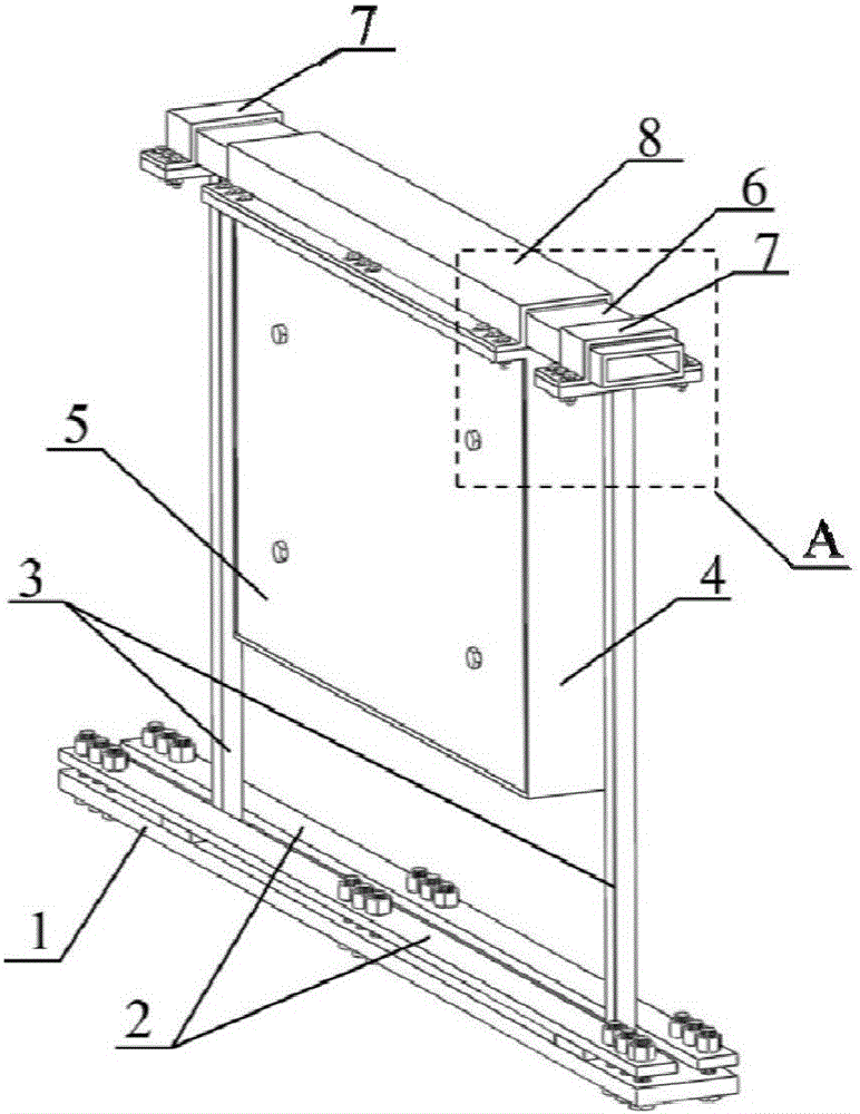
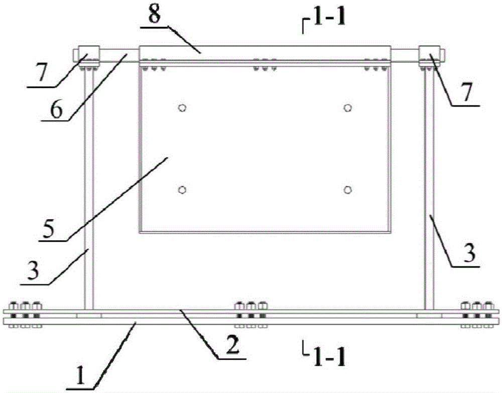
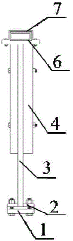
[0020] A frequency continuously adjustable mass damper comprises a bottom plate 1, a pressure plate 2, a column 3, a counterweight box 4, a counterweight steel plate 5 and a beam 6.

[0021] The overall schematic diagram, elevation and sectional view of the present invention are as follows: Figure 1-Figure 4 shown. Column 3 such as Figure 6 As shown, a rectangular column foot is set at the bottom, and a rectangular column cap is set at the top. The bolt I11 is pre-embedded or implanted into the structure where the damper needs to be installed, and the column foot of the column 3 is clamped and fixed between the bottom plate 1 and the pressure plate 2 by tightening the bolt I11. Before the upright is clamped and fixed, the foot of the upright 3 can move in the length direction of the bottom plate 1, so ...


PUM


Abstract

The invention belongs to the technical field of civil engineering structure vibration damping and provides a frequency continuously adjustable mass damper. The frequency continuously adjustable mass damper is mainly composed of stand columns, a weight box, weight steel plates, a cross beam, a bottom plate, pressing plates and the like. The frequency continuously adjustable mass damper is suitable for controlling high-frequency vibration in large-span sky bridges, port piers and large-span building structures. Compared with a traditional tuned mass damper, the cross beam is adopted to replace springs to provide rigidity of a damping system and reduce the high-frequency vibration. The stand columns are connected with the bottom plate and the pressing plates in a clamping mode, the mounting positions of the stand columns can be adjusted in the length direction of the cross beam, and then the span of the cross beam can be changed. The frequency of the damping system can be continuously adjusted by adjusting the span of the cross beam. The weight steel plates are vertically assembled and connected so that the mounting space can be reduced; meanwhile, the frequency of the damping system can be slightly adjusted by changing the number of the weight steel plates.

Description

technical field [0001] The invention belongs to the technical field of vibration reduction of civil engineering structures, and relates to a frequency continuously adjustable mass damper composed of a column, a counterweight box, a counterweight steel plate, a beam, a bottom plate and a pressure plate. Background technique [0002] A tuned mass damper (TMD for short) is a classic vibration control device, which is usually a vibration system composed of a spring, a damper and a mass. However, the tuned mass damper is a frequency-sensitive damping device, and there are the following problems in actual production: (1) The current tuned mass damper is usually provided by a spring, which is limited by the manufacturing process. The rigidity is difficult to produce accurately, which makes it difficult to guarantee the frequency of the damping system; (2) the current tuned mass damper usually changes the frequency of the system by changing the mass of the counterweight after the sp...

Claims


Application Information

Patent Timeline
Patent Type & Authority Patents(China)
IPC IPC(8): E04B1/98E01D19/00
Inventor 霍林生李旭李宏男
Owner DALIAN UNIV OF TECH
Why Eureka
Try Eureka