
Wearing part with a wear indicator and system for wear testing

A technology for indicating parts and wear status, applied in vehicle parts, tire parts, testing wear resistance, etc., can solve the problems of high cost, high quality, expensive sensors, etc., and achieve the effect of small failure rate

Active Publication Date: 2015-09-23
MAN NUTZFAHRZEUGE AG
View PDF16 Cites 6 Cited by
  • Summary
  • Abstract
  • Description
  • Claims
  • Application Information

AI Technical Summary

Problems solved by technology

However, sensors introduced into tires have the disadvantage that they are expensive and must be implemented robustly to make retreading or reconditioning possible
[0006] The above-mentioned systems for the reliable detection and evaluation of optical features require high quality and are therefore also expensive
In addition, depressions or protrusions in the tire can only be detected with difficulty using simple optical systems
Wear features in the form of indentations can also be filled with dirt, mud or other contaminants and additionally make measuring and identifying the features difficult
Due to the dark color of the tyres, the contrast between the rolling surface (Lauffläche) and the wear marks is so small that it cannot be reliably detected even in the absence of contamination
Measurement errors cannot therefore be ruled out in the methods known from the prior art

Method used


Image

  • Wearing part with a wear indicator and system for wear testing
  • Wearing part with a wear indicator and system for wear testing
  • Wearing part with a wear indicator and system for wear testing

Examples


Embodiment Construction

[0066] figure 1 A perspective view of a vehicle tire 1 is shown, in which a wear indicator in the form of a multi-layered QR® code 3 is introduced into the running surface 2 . The QR® code is implemented as an iQR code, which is especially suitable for cylindrical surfaces.

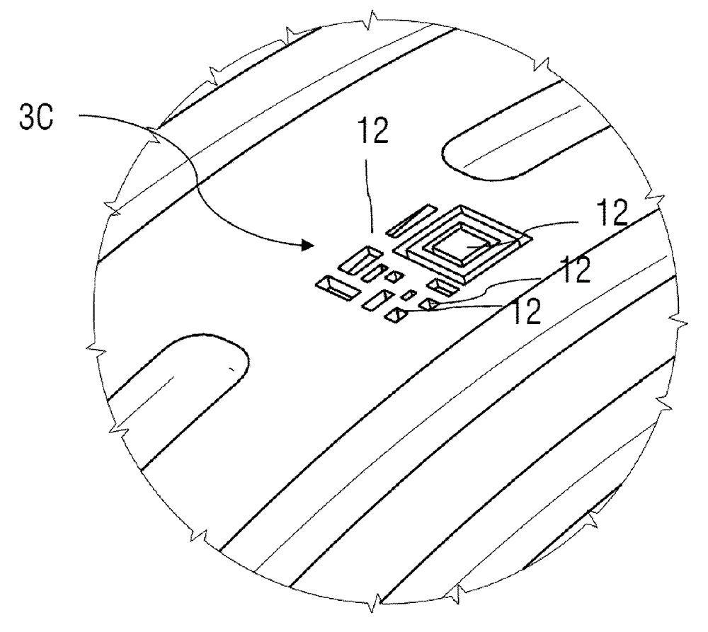
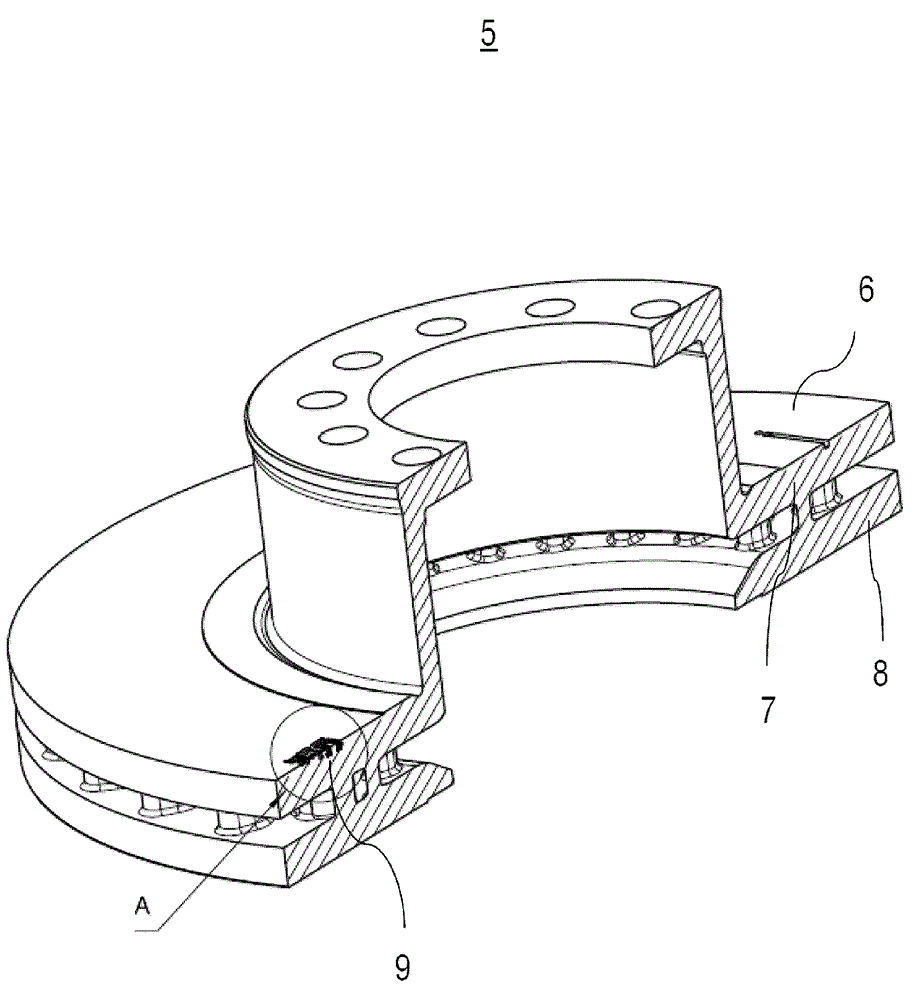
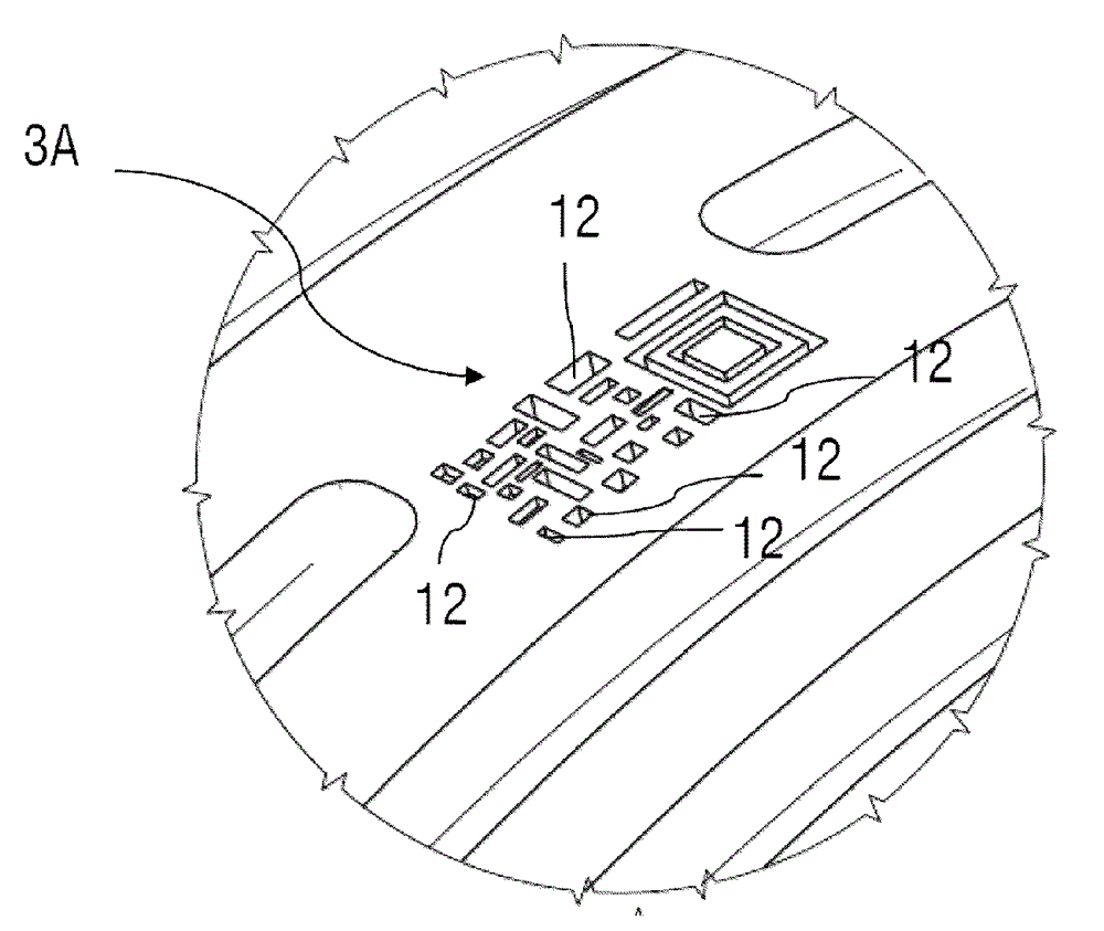
[0067] Figure 2A shown figure 1 An enlarged perspective view of part A of , and Figure 2B shown figure 1 An enlarged top view of part A of . Figure 2A and 2B In particular the uppermost plane 3A of the QR® code in the new state of the tire is shown.

[0068] The information carrier of the QR code, ie the black dots and stripes 12 of the QR code, are formed by the tire material. For reasons of simplified visibility and better visibility, only some of the dots or stripes of the QR® code are indicated with reference numeral 12 .

[0069] The gaps between the information carriers 12 are each embodied as recesses. The current form of the QR® code digitally describes the state of tire wear and other...


PUM


Abstract

A wearing part, preferably for a vehicle, contains a wear indicator whose appearance changes depending on a wear condition of the wearing part. The wear indicator contains a multidimensional pattern that is disposed on the wearing part such that different levels of the pattern are exposed depending on the wear condition.

Description

technical field [0001] The invention relates to a wear part, preferably for a vehicle, with a wear indicator whose appearance changes depending on the state of wear of the wear part. Furthermore, the invention relates to a system for wear inspection. [0002] An exemplary highlighted application of the invention concerns a tire as an example for a wear article, which is equipped with a wear indicator according to the invention. It is known from practice that the state of wear of tires must be regularly checked in order to monitor the functionality of the tires and to comply with legal regulations. For commercial vehicles, tires can be reconditioned (nachschneiden) a maximum of two times and retreaded (runderneuern) once after reaching the wear limit. In order to assess when the tire or the tread profile (Profil) must be replaced or renewed (erneuern), wear indicators and wear predictions are used. Background technique [0003] Methods are known from the prior art, for exa...

Claims


Application Information

Patent Timeline
Patent Type & Authority Applications(China)
IPC IPC(8): B60C11/24G01N3/56
CPCG06K19/06037G06K19/06159G06K19/06028F16D66/02F16D65/12B60C11/24F16D65/127F16D2065/1332B60C11/246
Inventor M.布茨
Owner MAN NUTZFAHRZEUGE AG
Learn More