
Handpiece having direct cooling type slimmed driving part

A technology of driving parts and handpieces, applied in fixed tubular catheter components, surgery, manufacturing tools, etc., can solve problems such as injection of salt water, reduction of heat cooling effect, vibration and noise, etc., to prevent engine overheating, realize miniaturization, Realize the effect of light weight

Active Publication Date: 2015-09-16
MICRO NX
View PDF7 Cites 4 Cited by
  • Summary
  • Abstract
  • Description
  • Claims
  • Application Information

AI Technical Summary

Problems solved by technology

[0005] However, in the conventional method of using salt water as described above, the pipes for supplying salt water are formed outside the stator, and the pipes formed outside indirectly cool the heat generated from the high-speed engine, so the cooling effect on the heat of the high-speed engine is very small. , there is also the disadvantage of continuously injecting brine, and the structure of the electrical method is complicated, and the cooling effect on the heat generated from the high-speed engine is also reduced
[0006] Moreover, the existing way of using air can only cool the space around the rotating impeller due to the unsmooth flow of the air, but cannot cool the interior of the handpiece and the high-speed engine as a whole
[0007] Therefore, in the past, the heat generated when the high-speed engine of the handpiece was running could not be effectively cooled, and there was a problem of vibration and noise when the high-speed engine of the handpiece was running.

Method used


Image

  • Handpiece having direct cooling type slimmed driving part
  • Handpiece having direct cooling type slimmed driving part
  • Handpiece having direct cooling type slimmed driving part

Examples


Embodiment Construction

[0020] Hereinafter, specific contents for implementing the present invention will be described in more detail with reference to the accompanying drawings.

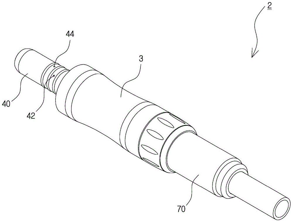
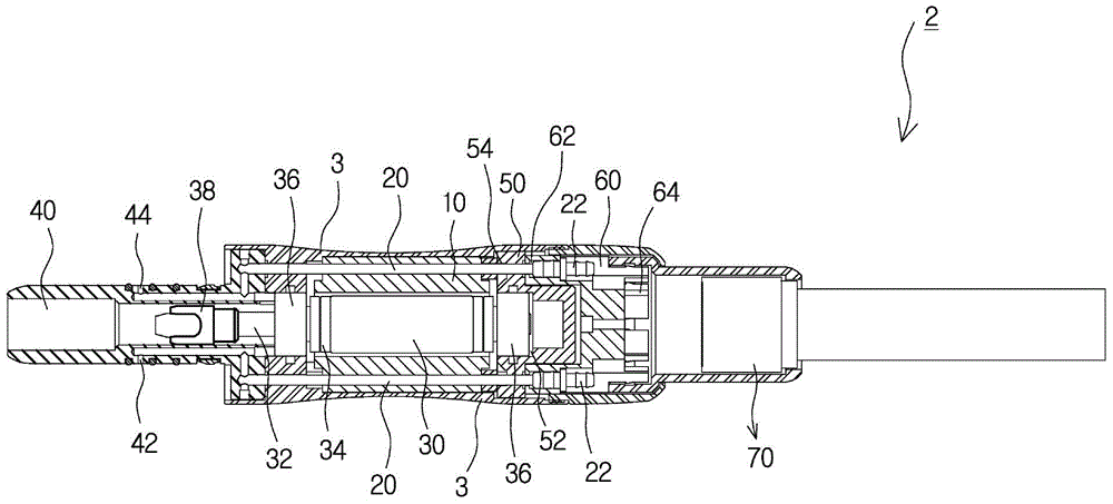
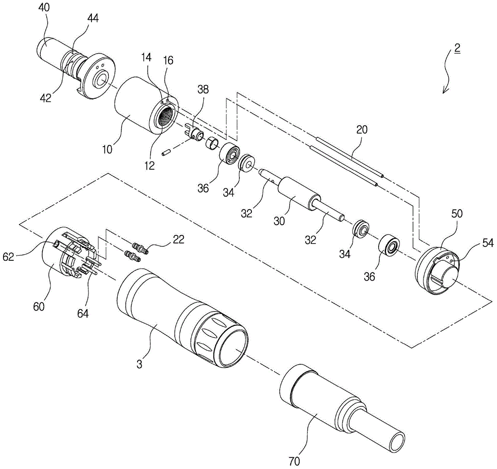
[0021] refer to Figure 1 to Figure 4 , according to the handpiece with direct cooling light-duty driving part of the present invention, it includes an outer shell (3) that is shaped like a stick and can be held by hand, is inserted into the inner side of the outer shell (3), and is formed with a ventilation hole ( 14) and the cylindrical magnetic core (10) of water injection hole (16), the pipeline (20) that is respectively inserted in the ventilation hole (14) of described magnetic core (10) and water injection hole (16) and forms, by A rotor (30) formed of a cylindrical magnet inserted inside the magnetic core (10), and a cylindrical support on both sides of a transmission shaft (32) coupled to the rotor (30) are respectively sandwiched. ring (34), a pair of bearings (36) arranged in front and rear of the support ring ...


PUM


Abstract

The handpiece includes; an outer housing of a bar shape; a cylindrical core inserted into the outer housing and having an air hole and a water hole; pipes respective inserted into the air hole and the water hole of the core; a rotor made with a cylindrical magnetic material and inserted into the core; cylindrical support rings forcedly fit to both sides of transfer shafts of the rotor; a pair of bearings respectively disposed at the front side and the rear side of the support rings; a coupling disposed in front of the rotor; a front housing joined to the front of the outer housing; a front cap disposed at the rear of the core; a rear cap disposed at the rear of the front cap and having a power supply terminal disposed at one side thereof; and a rear housing joined to the rear of the outer housing.

Description

technical field [0001] The present invention relates to a handpiece with a direct-cooling light-duty driving part, and more particularly relates to a through hole formed through the engine stator by combining water and air pipes for inflowing water and air in order to cool the heat generated by the engine when the engine is running inside the handpiece , thus, the heat generated from the engine can be effectively cooled, and by combining the pipes with the through holes of the stator, the handpiece with the direct cooling type lightweight drive section can be reduced in size and light in weight . Background technique [0002] Generally, handpieces are used in dental crafts such as cutting or grinding teeth in dentistry, nail art used in manicures at nail salons, fine work such as processing gemstones, etc., and are mainly used in fields that require precision machining. [0003] At this time, the handpiece is provided with a high-speed engine that supplies power and runs at...

Claims


Application Information

Patent Timeline
Patent Type & Authority Applications(China)
IPC IPC(8): A61C1/08A61C1/06B25D17/20
CPCA61B2017/1651A61C1/0061F28D7/16A61B17/1622A61C1/06
Inventor 李钟建
Owner MICRO NX
Learn More