Multistage liquefaction apparatus driven by loop thermoacoustic engine

A technology of thermoacoustic engine and liquefaction device, applied in liquefaction, refrigeration and liquefaction, gas cycle refrigerator, etc., can solve the problems of increasing system complexity and restricting applications, achieve good application prospects, reduce production costs, reduce transmission The effect of heat loss

Active Publication Date: 2015-09-16
TECHNICAL INST OF PHYSICS & CHEMISTRY - CHINESE ACAD OF SCI
View PDF7 Cites 6 Cited by
  • Summary
  • Abstract
  • Description
  • Claims
  • Application Information

AI Technical Summary

Problems solved by technology

This undoubtedly increases the complexit...

Method used


Image

  • Multistage liquefaction apparatus driven by loop thermoacoustic engine
  • Multistage liquefaction apparatus driven by loop thermoacoustic engine
  • Multistage liquefaction apparatus driven by loop thermoacoustic engine

Examples


Embodiment 1

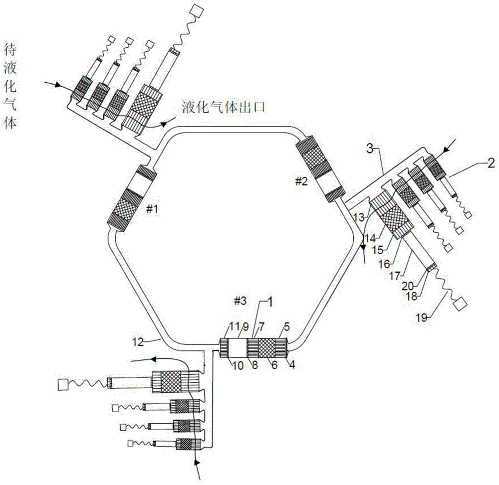
[0027] figure 2 It is a structural schematic diagram of a gas multistage liquefaction device (embodiment 1) driven by a loop multistage thermoacoustic engine of the present invention; as figure 2 As shown, the gas multi-stage liquefaction device in this embodiment 1 consists of 3 (#1 thermoacoustic engine unit, #2 thermoacoustic engine unit and #3 thermoacoustic engine unit) identical thermoacoustic engine units and 3 bypass 3 components; 3 thermoacoustic engine units are connected end to end through a resonance tube 12 to form a loop structure; each bypass 3 is connected to 4 pulse tube refrigerator units 2, and the size is from the far end far away from the resonance tube 12 to the proximal end From small to large; each bypass is at the junction of the outlet of the engine sub-cooler 11 and the resonant tube 12;

[0028] Each stage of thermoacoustic engine unit 1 is composed of DC suppressor 4, engine main cooler 5, engine regenerator 6, heater 7, high temperature end lam...

Embodiment 2

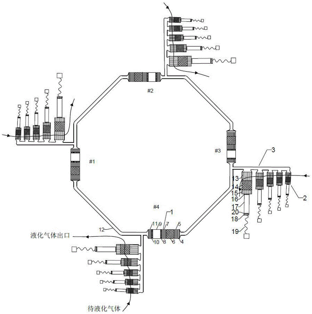
[0033] image 3 It is a structural schematic diagram of a gas multistage liquefaction device (embodiment 2) driven by a loop multistage thermoacoustic engine of the present invention; as image 3 As shown, the gas multistage liquefaction device of the present embodiment 2 consists of 4 (#1 thermoacoustic engine unit, #2 thermoacoustic engine unit, #3 thermoacoustic engine unit and #4 thermoacoustic engine unit) identical (length and Cross-sectional area) thermoacoustic engine unit and four bypasses 3; the thermoacoustic engine units at all levels are connected end-to-end through resonant tubes 12 of the same size to form a loop structure; each bypass 3 is connected to 5 size by Small to large pulse tube refrigerator units 2; each stage of bypass is at the connection between the outlet of each engine subcooler 11 and the resonant tube 12;

[0034] Each stage of thermoacoustic engine unit 1 is composed of DC suppressor 4, engine main cooler 5, engine regenerator 6, heater 7, hi...


PUM


Abstract

The invention discloses a multistage liquefaction apparatus driven by a loop thermoacoustic engine, which comprises an N-grade thermoacoustic engine units and bypasses, wherein the N-grade thermoacoustic engine unit is formed by connecting resonating tubes end to end in a loop; each bypass is connected to M-grade vascular refrigerating machine units from small to large; N=3-6, and M=4-10; when the apparatus works, an engine heater is heated to a high temperature, a temperature gradient is formed by a heat regenerator, a reciprocating oscillation pressure is generated by the system in the heat regenerator for thermoacoustic transition, and a low temperature is kept from a cold head heat pump to a main cooler output cold head; the cold head temperature from grade 1 to grade M-1 refrigerating machine is reduced in equivalent to a gas liquefaction temperature; the cold head of grade M is kept in the liquefaction temperature; when the liquefied gas passes through all cold heads in the sequence from temperature high to temperature low to complete the process of liquefaction, the liquefaction process from gas in normal temperature to liquid in liquefaction temperature is complete; the temperature of the gas can be reduced effectively step by step through the multistage vascular refrigerating machine of the bypass, and can reduce heat transfer loss; the vascular refrigerating machines are arranged from small to large to be reasonable for acoustic power distribution; the structure and size of each engine unit are same, which is favorable for batch production and reducing production cost.

Description

technical field [0001] The invention belongs to the field of gas liquefaction, in particular to a gas multistage liquefaction device driven by a loop multistage thermoacoustic engine. Background technique [0002] Liquefaction is the process by which a substance changes from a gaseous state to a liquid state. Since the volume of the gas after liquefaction will become one thousandth of its original volume, which is convenient for storage and transportation, some gases are usually liquefied in reality. There are two ways to achieve liquefaction, one is to lower the temperature, and the other is to compress the volume. Any gas can be liquefied when the temperature drops low enough. Therefore, how to manufacture a low-temperature refrigerator with high reliability, long life and low cost has become a concern. [0003] Thermoacoustic phenomenon is the process of mutual conversion between thermal energy and mechanical energy between oscillating fluid and solid wall. One of its ...

Claims


Application Information

Patent Timeline
IPC IPC(8): F25B9/14
CPCF25J1/001F25B9/145F25B2309/1407F25B2309/1425F25B2309/1426F25J1/0015F25J1/0022F25J1/0225F25J2270/91F25J2210/42F25J2210/60F25J2215/10
Inventor 罗二仓徐静远张丽敏胡剑英吴张华戴巍余国瑶王晓涛
Owner TECHNICAL INST OF PHYSICS & CHEMISTRY - CHINESE ACAD OF SCI
Why Eureka
Try Eureka