Eureka AIR delivers breakthrough ideas for toughest innovation challenges, trusted by R&D personnel around the world.

Wheel side motor driving system and wheel side motor driving axle

A technology of wheel side motor and drive system, which is applied in the field of wheel side motor drive system and wheel side motor drive bridge, which can solve the problems of low motor power, poor transmission efficiency, narrow middle channel, etc., and achieve improved installation accuracy and comfort , is conducive to the effect of adjustment

Active Publication Date: 2015-09-16
JASMIN INT AUTO RES ANDDEV BEIJING CO LTD
View PDF9 Cites 11 Cited by
  • Summary
  • Abstract
  • Description
  • Claims
  • Application Information

AI Technical Summary

Problems solved by technology

[0003] At present, the structure of most vehicle drive systems (especially the drive system of new energy vehicles) is that the central motor is connected to a traditional rear axle through the transmission shaft. The floor layout needs to achieve drive anti-skid control and body stability control through braking, and the wheel motor drive axle has become an important research direction at home and abroad. This drive axle generally includes drive motors, reducer mechanisms, wheel hubs and other components. , replacing the engine, clutch, gearbox, transmission shaft, differential and other components, simplifying the overall mechanism and improving transmission efficiency
[0004] However, the existing wheel-side motor drive axles and the wheel-side motor drive systems therein have disadvantages such as low motor power, small torque, low speed, heavy weight, narrow middle channel, and high noise.

Method used


Image

  • Wheel side motor driving system and wheel side motor driving axle
  • Wheel side motor driving system and wheel side motor driving axle
  • Wheel side motor driving system and wheel side motor driving axle

Examples


Embodiment Construction

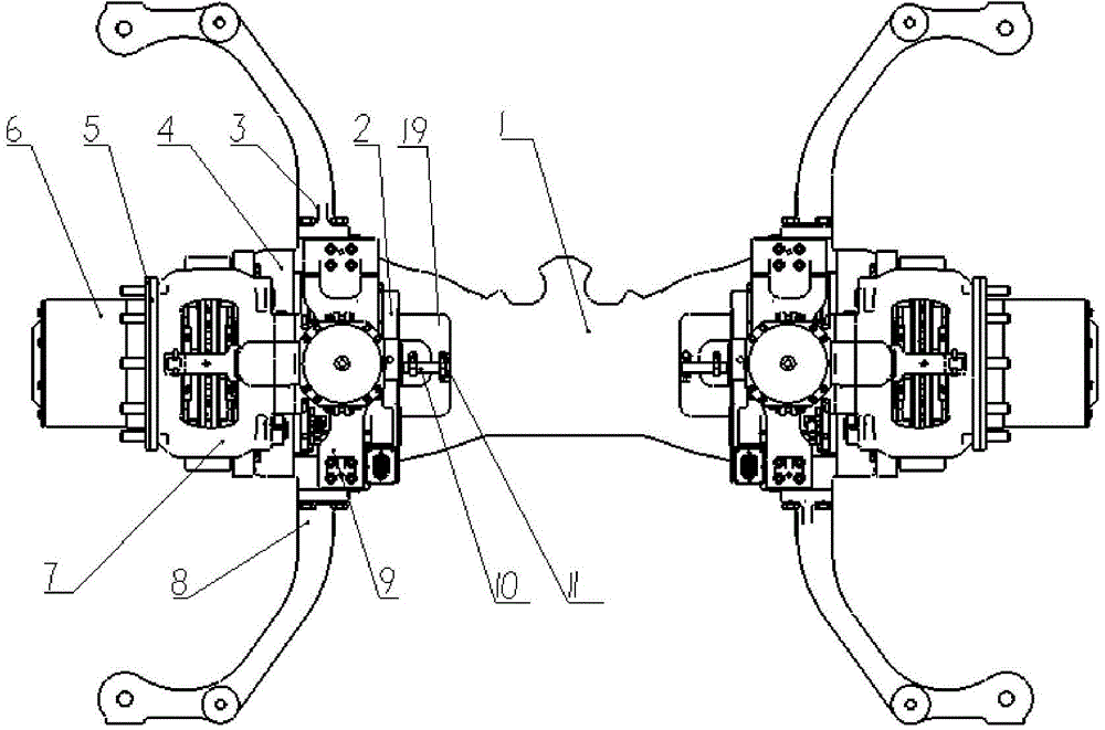
[0037] In order to make the purpose, technical solutions and advantages of the embodiments of the present invention clearer, the technical solutions in the embodiments of the present invention will be clearly and completely described below in conjunction with the drawings in the embodiments of the present invention. Obviously, the described embodiments It is a part of embodiments of the present invention, but not all embodiments. Based on the embodiments of the present invention, all other embodiments obtained by persons of ordinary skill in the art without making creative efforts belong to the protection scope of the present invention. The "left" and "right" involved in the present invention all refer to figure 1 The orientation prevails.

[0038] refer to figure 1 , an embodiment of the in-wheel motor drive axle of the present invention includes an embodiment of the in-wheel motor drive system of the present invention.

[0039] Among them, refer to Figure 1 to Figure 9 ...


PUM


Abstract

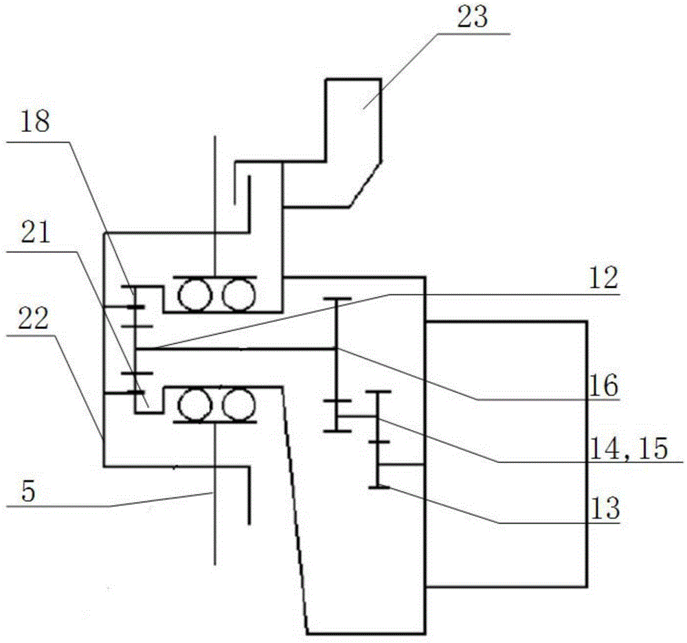
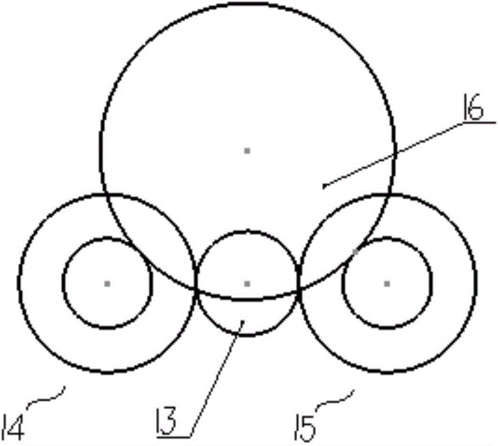
The invention relates to a wheel side motor driving system and a wheel side motor driving axle. The wheel side motor driving system comprises a main speed reducer assembly (4), a wheel side speed reducer assembly (6) and a hub assembly (5). The main speed reducer assembly comprises an output gear (16); the wheel side speed reducer assembly comprises a sun wheel shaft (12), a planet wheel (18), a wheel reduction shell (22) and a planet frame (31); the output gear of the main speed reducer assembly is connected with the sun wheel shaft in a power transmission manner, and the sun wheel shaft is meshed with the planet wheel; the planet wheel is arranged on the planet frame in a power transmission manner, and the planet frame is arranged in the wheel reduction shell in a power transmission manner; the wheel reduction shell is connected with the hub assembly in a power transmission manner; and the wheel side motor driving axle comprises the wheel side motor driving system. Compared with the prior art, the wheel side motor driving system and the wheel side motor driving axle have the advantage that rim space is effectively utilized, and the speed ratio is increased.

Description

technical field [0001] The invention relates to the field of automobiles, in particular to a wheel-side motor drive system and a wheel-side motor drive axle. Background technique [0002] With the gradual withering of oil resources and the gradual increase of air pollution, the society is increasingly calling for new energy vehicles, including pure electric, hybrid, plug-in, fuel cell and other forms of vehicles. New energy vehicles greatly reduce the impact on Oil dependence and air pollution. Compared with traditional internal combustion engine vehicles, new energy vehicles have undergone tremendous changes in both the general layout of the vehicle and the drive system assembly due to the different forms of energy supply. The drive system assembly is crucial to the vehicle. Important, it not only undertakes the carrying function and driving function, but also directly determines the safety and comfort performance of the vehicle. [0003] At present, the structure of most...

Claims


Application Information

Patent Timeline
IPC IPC(8): B60K7/00B60K17/28B60K17/08
Inventor 陈言平吴阳年汪成应雷继彬
Owner JASMIN INT AUTO RES ANDDEV BEIJING CO LTD
Why Eureka
Eureka Blog
Learn More