
Negative ion-based neutral beam injector

An injector, negative ion technology, used in ion beam tubes, climate sustainability, radiation/particle processing, etc., to solve problems such as unproven stable operation

Active Publication Date: 2015-09-09
TRI ALPHA ENERGY INC
View PDF1 Cites 16 Cited by
  • Summary
  • Abstract
  • Description
  • Claims
  • Application Information

AI Technical Summary

Problems solved by technology

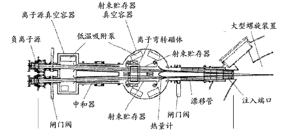
[0028] Currently, high-energy neutral beam injectors under development for next-stage melting devices (e.g., ITER tokmaks) have not proven stable operation at the desired energy of 1 MeV and with sufficiently high currents. Steady state or continuous wave (CW)

Method used


Image

  • Negative ion-based neutral beam injector
  • Negative ion-based neutral beam injector
  • Negative ion-based neutral beam injector

Examples


Embodiment Construction

[0058]The additional features and teachings disclosed below can be utilized alone or in combination with other features and techniques to provide new negative ion based neutral beam injectors. Representative examples of embodiments described herein, which utilize many of these additional features and teachings, both individually and in combination, will now be described in more detail with reference to the accompanying drawings. This detailed description is intended merely to teach those skilled in the art further details for practicing preferred aspects of the present teachings, and is not intended to limit the scope of the invention. Thus, combinations of features and steps disclosed in the following Detailed Description are not necessary to practice the invention in the broadest sense, and are instead taught merely to particularly describe representative examples of the teachings.

[0059] Furthermore, the various features of the representative examples and the dependent cl...


PUM


Abstract

A negative ion-based neutral beam injector comprising a negative ion source, accelerator and neutralizer to produce about a 5 MW neutral beam with energy of about 0.50 to 1.0 MeV. The ions produced by the ion source are pre-accelerated before injection into a high energy accelerator by an electrostatic multi-aperture grid pre-accelerator, which is used to extract ion beams from the plasma and accelerate to some fraction of the required beam energy. The beam from the ion source passes through a pair of deflecting magnets, which enable the beam to shift off axis before entering the high energy accelerator. After acceleration to full energy, the beam enters the neutralizer where it is partially converted into a neutral beam. The remaining ion species are separated by a magnet and directed into electrostatic energy converters. The neutral beam passes through a gate valve and enters a plasma chamber.

Description

technical field [0001] The subject matter disclosed herein relates generally to neutral beam injectors, and more particularly to negative ion-based neutral beam injectors. Background technique [0002] Until now, neutral beams used in magnetic melting research, materials processing, etching, sterilization, and other applications were formed from positive ions. The positive hydrogen isotope ions are extracted and accelerated from a gas discharge plasma by an electrostatic field. After the accelerator's ground plane, they enter the gas chamber, where they undergo both charge exchange reactions to gain electrons and impact ionization reactions to lose electrons again. Since the charge exchange profile decreases with increasing energy faster than ionization, the equilibrium neutral fraction in thick gas cells begins to drop rapidly at energies greater than 60 keV for hydrogen particles. For hydrogen isotope neutral beam applications requiring slightly higher energies than this...

Claims


Application Information

Patent Timeline
IPC IPC(8): G21B1/15
CPCG21B1/15Y02E30/16G21K1/00H05H3/02H05H7/08H05H2007/082H01J27/08H05H7/22Y02E30/10
Inventor Y.I.贝尔钦科A.V.伯达科夫V.I.戴维登科G.I.迪莫夫A.A.伊瓦诺夫V.V.科贝茨A.N.斯米尔诺夫M.W.宾德鲍尔D.L.塞维尔T.E.理查森
Owner TRI ALPHA ENERGY INC
Learn More