
In-situ carbon and oxide doping of atomic layer deposition silicon nitride films

A technology of silicon carbonitride and silicon carbonitride, which is applied in the field of thin film deposition, can solve the problems of electrical performance degradation, low yield, low cleaning and etching rate, etc.

Inactive Publication Date: 2015-09-09
APPLIED MATERIALS INC
View PDF0 Cites 11 Cited by
  • Summary
  • Abstract
  • Description
  • Claims
  • Application Information

AI Technical Summary

Problems solved by technology

However, a high percentage of carbon in the film produces a low cleaning etch rate but degrades the electrical performance
On the other hand, a high percentage of oxygen or nitrogen in the film improves electrical properties at the expense of low clean etch rates
Traditional process technology based on low throughput due to huge amount of pumping / rinsing time even with high volume batch processes
Also, controlling process parameters like gas flow, plasma uniformity is a huge disadvantage for giant furnaces

Method used


Image

  • In-situ carbon and oxide doping of atomic layer deposition silicon nitride films
  • In-situ carbon and oxide doping of atomic layer deposition silicon nitride films
  • In-situ carbon and oxide doping of atomic layer deposition silicon nitride films

Examples


Embodiment Construction

[0014] Embodiments disclosed herein relate generally to processing of substrates, and more specifically, to methods for forming dielectric films. In one embodiment, the method includes placing a plurality of substrates inside a processing chamber, and performing the sequence of exposing the substrates to a first reactive gas comprising silicon, and then exposing the substrates to exposing the substrate to a plasma of a second reactive gas comprising at least one of nitrogen and oxygen or carbon, and repeating the sequence to form silicon carbonitride or silicon oxycarbonitride on each of the substrates the dielectric film.

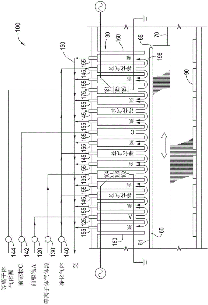
[0015] figure 1 is a cross-sectional side view of a processing chamber 100 according to one embodiment. The processing chamber 100 is capable of performing one or more deposition processes on one or more substrates 60 . The processing chamber 100 includes a gas / plasma distribution assembly 30 capable of distributing one or more gases and / or plasma acros...


PUM


Abstract

Embodiments disclosed herein generally relate to the processing of substrates, and more particularly, relate to methods for forming a dielectric film. In one embodiment, the method includes placing a plurality of substrates inside a processing chamber and performing a sequence of exposing the substrates to a first reactive gas comprising silicon, and then exposing the substrates to a plasma of a second reactive gas comprising nitrogen and at least one of oxygen or carbon, and repeating the sequence to form the dielectric film comprising silicon carbon nitride or silicon carbon oxynitride on each of the substrates.

Description

technical field [0001] Embodiments disclosed herein relate generally to methods for depositing thin films, and more specifically, to methods for depositing SiCN or SiCON films using atomic layer deposition. Background technique [0002] In the decades since the introduction of semiconductor devices, the size of semiconductor device geometries has decreased significantly. Modern semiconductor fabrication equipment typically produces devices with feature sizes of 45nm, 32nm, and 28nm, and new equipment is being developed and implemented to fabricate devices with dimensions smaller than 12nm. In addition, chip construction is going through a turning point from two-dimensional structures to three-dimensional structures in order to obtain devices with better performance and lower power consumption. Consequently, conformal deposition of materials used to form these devices has become increasingly important. [0003] As device nodes shrink below 45nm, there is a need for conforma...

Claims


Application Information

Patent Timeline
Patent Type & Authority Applications(China)
IPC IPC(8): H01L21/31
CPCC23C16/24C23C16/345C23C16/458C23C16/347C23C16/50C23C16/45525C23C16/30C23C16/36C23C16/45531C23C16/45542C23C16/45551
Inventor V·恩古耶M·巴尔塞努N·李S·D·马库斯M·沙立D·汤普森L-Q·夏
Owner APPLIED MATERIALS INC
Learn More