
A miniature ultra-wideband bandpass lc filter

An LC filter and ultra-wideband technology, applied in the field of filters, can solve the problems of increased insertion loss of surface acoustic wave filters, difficulty in taking into account performance and volume, and inability to guarantee various parameters, achieving low insertion loss, conducive to Stable, highly rectangular effect

Active Publication Date: 2018-10-02
北京中科飞鸿科技股份有限公司
View PDF5 Cites 2 Cited by
  • Summary
  • Abstract
  • Description
  • Claims
  • Application Information

AI Technical Summary

Problems solved by technology

[0003] However, there is a certain degree of paradox between the size and performance of the filter. In the prior art, taking the 21.4MHz frequency band as an example, it usually requires Surface acoustic wave filters are used, but with the increase of frequency bandwidth, the insertion loss of surface acoustic wave filters also increases, and the difficulty of realization is also increasing. At present, the existing surface acoustic wave filters operate at 21.4MHz frequency However, if the bandwidth reaches 20MHz at this frequency point, it is difficult for the corresponding LC filter to take into account the performance and size, that is, there are the following problems: if the Q value of the inductor is guaranteed, then The minimum size can only be 27mm*15mm*10mm; if it is reduced to the same size, the parameters related to the Q value cannot be guaranteed

Method used


Image

  • A miniature ultra-wideband bandpass lc filter
  • A miniature ultra-wideband bandpass lc filter
  • A miniature ultra-wideband bandpass lc filter

Examples


Embodiment Construction

[0028] In order to make the objectives, technical solutions and advantages of the present invention clearer, the present invention will be further described in detail below with reference to the accompanying drawings.

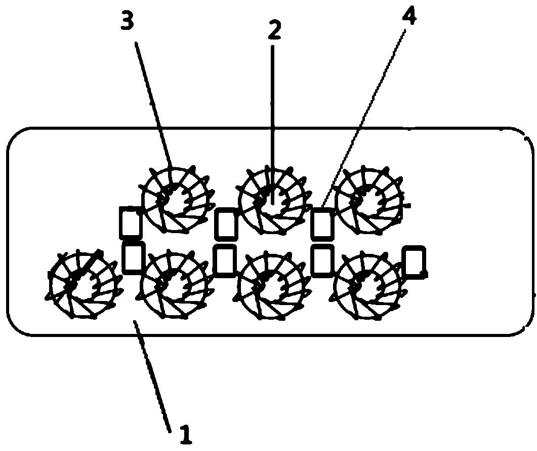
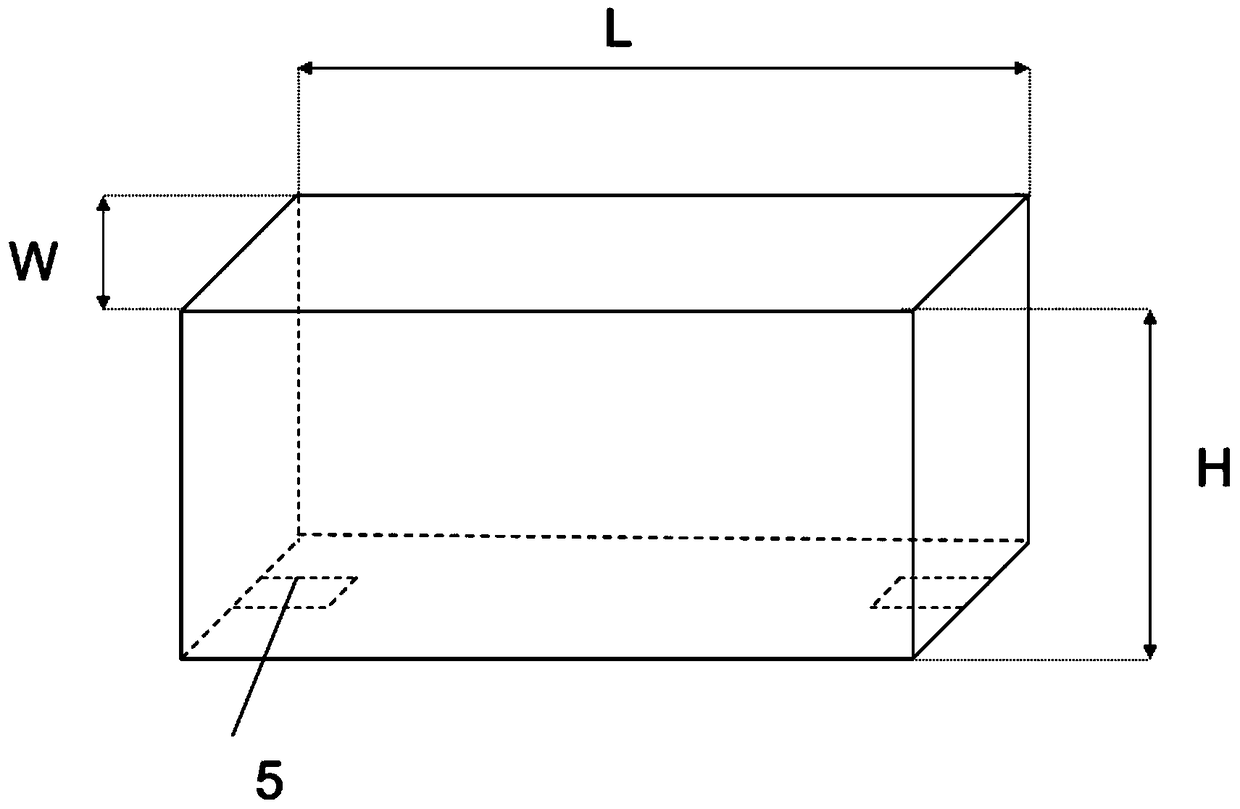
[0029] Embodiments of the present invention provide a miniature ultra-wideband bandpass LC filter, such as figure 1 As shown, it includes a PCB base 1, a winding magnetic ring 2 and a capacitor 4. The PCB base 1 has three layers. The PCB base 1 is 0.5mm thick, 5.5mm wide, and 13mm long. The capacitor 4 and the winding The magnetic rings 2 are all fixed on the top layer of the PCB by soldering. The winding magnetic ring 2 is sheathed with an externally wound enameled wire 3. The magnetic inductance coefficient of the winding magnetic ring 2 is stable and has a The advantage of high stability;

[0030] The bottom layer of the PCB base 1 includes a grounded area and a non-grounded area, and the non-grounded area is a rectangular pad 5 symmetrically arranged at th...


PUM


Abstract

The invention provides a micro ultra-wide-band band-pass LC filter. According to the filter, winding magnetic rings with small temperature drift, good stability, and high Q value are employed, and 0603 packaging capacitors are employed so that the electrical performance index of the filter is greatly increased; a special shell package is provided so that the mechanical performance of the filter can be enhanced, and the filter can be applied in the severe environment; and the design of a three-layer structure at a PCB is provided so that signal interference can be effectively shielded, and input, output, and grounding signals can be perfectly transmitted to the PCB and components. According to the micro ultra-wide-band band-pas LC filter, based on the design principle of small size, ultra-large bandwidth, and high rectangular degree, a transfer function expansion equation of the filter is designed, the match of the capacitors and inductors is realized strictly according to equation parameters, and the filter is advantaged by many mechanical and electrical performances such as micro packaging, ultra-large bandwidth, low insertion loss, high rectangular degree, and high stop-band suppression etc.

Description

technical field [0001] The invention relates to the field of filters, in particular to a miniature ultra-wideband bandpass LC filter. Background technique [0002] With the development of radio frequency technology, the requirements for the filter frequency index are becoming more and more stringent. The transceiver channels of some commonly used communication equipment need to use filters with larger bandwidths to meet the increasing information transmission volume and wide frequency bandwidth. But at the same time, the requirements for volume are becoming more and more stringent, and the volume must be developed towards "miniaturization". Under this premise, a broadband bandpass filter with "small insertion loss", "small size", "small in-band fluctuation", "good rectangular coefficient" and "stable performance" is urgently needed. [0003] However, there is a certain degree of paradox between the volume and performance of the filter. In the prior art, taking the 21.4MHz f...

Claims


Application Information

Patent Timeline
Patent Type & Authority Patents(China)
IPC IPC(8): H03H7/01
Inventor 李洪万飞杨思川陈明和黄歆李凯
Owner 北京中科飞鸿科技股份有限公司
Learn More