
Unmanned underwater vehicle (UUV) track tracking control optimization method under environmental interference

A technology for unmanned aerial vehicles and track tracking, which is applied in three-dimensional position/channel control and other directions, and can solve the problem of low accuracy of UUV track tracking control

Inactive Publication Date: 2015-09-02
HARBIN INST OF TECH
View PDF4 Cites 33 Cited by
  • Summary
  • Abstract
  • Description
  • Claims
  • Application Information

AI Technical Summary

Problems solved by technology

[0003] The purpose of the present invention is to solve the problem of low accuracy of the existing UUV track tracking control, and proposes an underwater unmanned vehicle track tracking control optimization method under environmental interference

Method used


Image

  • Unmanned underwater vehicle (UUV) track tracking control optimization method under environmental interference
  • Unmanned underwater vehicle (UUV) track tracking control optimization method under environmental interference
  • Unmanned underwater vehicle (UUV) track tracking control optimization method under environmental interference

Examples


specific Embodiment approach 1

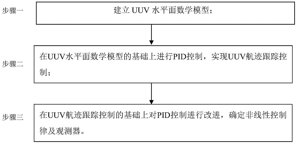
[0016] Specific implementation mode one: combine figure 1 Illustrate this embodiment, the underwater unmanned aerial vehicle track tracking control optimization method under environmental interference is specifically carried out according to the following steps:

[0017] Step 1. Establish a UUV horizontal plane mathematical model;

[0018] Step 2. On the basis of the UUV horizontal plane mathematical model, perform PID control on the unmanned aerial vehicle to realize UUV track tracking control;

[0019] Step 3: Improve the PID control on the basis of the UUV track tracking control, and determine the nonlinear control law and observer.

specific Embodiment approach 2

[0020] Embodiment 2: The difference between this embodiment and Embodiment 1 is that the UUV horizontal plane mathematical model is established in the step 1; the specific process is:

[0021] (1) Establishment of kinematic equations:

[0022] Let the UUV center of gravity pose matrix in the earth coordinate system be η=[x,y,ψ] T , the angular velocity matrix in the earth coordinate system is The angular velocity matrix in the carrier coordinate system is V=[u,v,r] T ;

[0023] According to the conversion relationship between the earth coordinate system and the carrier coordinate system, the kinematic equation is obtained:

[0024] x . = u cos ψ - v sin ψ y . ...

specific Embodiment approach 3

[0066] Specific embodiment three: the difference between this embodiment and specific embodiment one or two is that: in the said step two, on the basis of the UUV horizontal plane mathematical model, the unmanned aerial vehicle is controlled by PID to realize the UUV track tracking control; The specific process is:

[0067] PID control algorithm:

[0068] ψ e = ψ d -ψ

[0069] where, ψ d is the real-time expected heading, which is the expected value artificially set by programming, ψ is the actual heading value when the UUV is sailing, and ψe is the heading error;

[0070] The PID control law of UUV heading is: ψ = k p · ψ e + k i · ∫ ψ e + k d · ψ . e ...


PUM


Abstract

The present invention relates to a UUV track tracking control optimization method under environmental interference, and aims to solve the existing problem that the accuracy of the conventional UUV track tracking control is low. The UUV track tracking control optimization method under the environmental interference is realized by the following technical scheme having a step 1 of establishing a UUV horizontal plane mathematical model; a step 2 of carrying out the PID control on the basis of the UUV horizontal plane mathematical model, and realizing the UUV track tracking control; a step 3 of improving the PID control on the basis of the UUV track tracking control, and determining a nonlinear control law and an observer. The UUV track tracking control optimization method under the environmental interference is applied to the UUV field.

Description

technical field [0001] The invention relates to an optimization method for track tracking control of an underwater unmanned vehicle. Background technique [0002] Unmanned underwater vehicle (UUV) has become a hot topic of research in various countries in recent years, and has been applied in various fields of underwater operations. Whether it is in the marine military field or in daily underwater applications, it is inseparable from the application and control of UUV. The traditional UUV track control adopts the classic PID control. The PID control in the classic control theory has the longest history and the widest application. The most powerful method of control. It is the abbreviation of proportional integral differential control, and its principle is to control the system error. The "error" mentioned here is the difference between the expected value and the output value. The error value is used as the input of the PID controller, and the PID controller is expressed a...

Claims


Application Information

Patent Timeline
Patent Type & Authority Applications(China)
IPC IPC(8): G05D1/10
Inventor 陈兴林高怡然于志亮崔宁徐川川耿光晓李松峰李松罗文嘉
Owner HARBIN INST OF TECH
Learn More