
Frequency-modulated continuous-wave radar based on on-chip directional coupler

A technology of directional coupler and frequency modulation continuous wave, which is applied in the direction of instruments, radio wave measurement systems, radio wave reflection/reradiation, etc. It can solve the problems of excessive volume, poor consistency, and difficulty in manufacturing, and achieve small size and compatibility Good performance and strong applicability

Active Publication Date: 2015-09-02
PEKING UNIV
View PDF5 Cites 0 Cited by
  • Summary
  • Abstract
  • Description
  • Claims
  • Application Information

AI Technical Summary

Problems solved by technology

Traditional circulators are composed of off-chip components, which have disadvantages such as oversized, high cost, difficult to manufacture, and poor consistency

Method used


Image

  • Frequency-modulated continuous-wave radar based on on-chip directional coupler
  • Frequency-modulated continuous-wave radar based on on-chip directional coupler
  • Frequency-modulated continuous-wave radar based on on-chip directional coupler

Examples


Embodiment 1

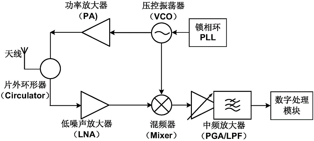
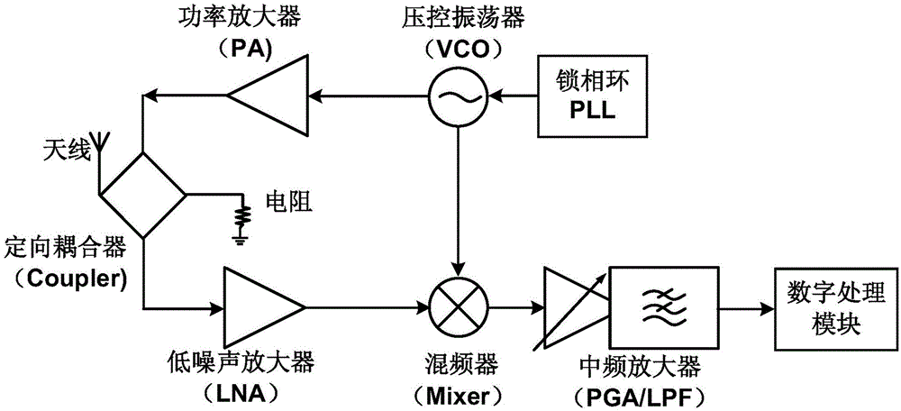
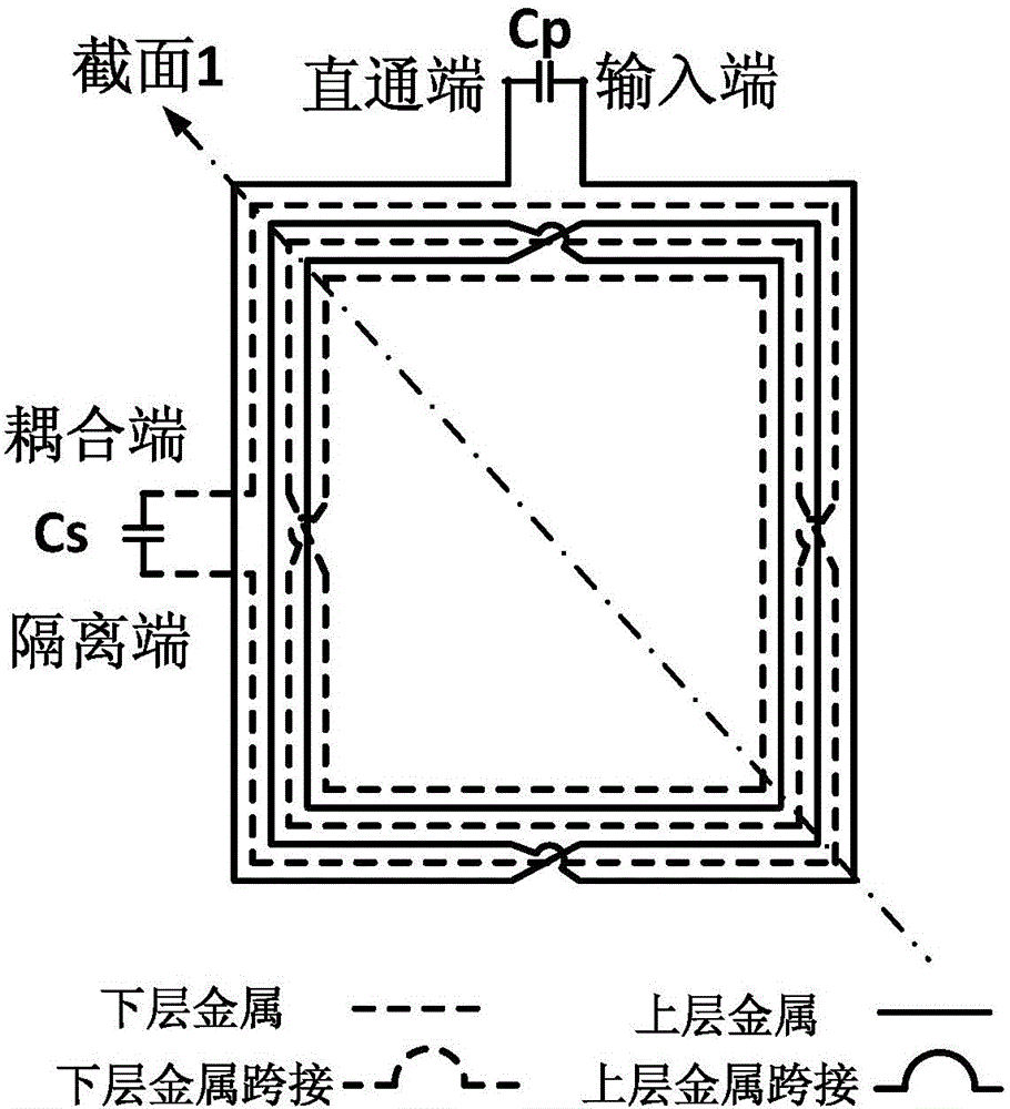
[0031] like figure 2 Shown in the IBM8HP0.13um SiGe process to achieve an on-chip directional coupler-based FM continuous wave radar, including phase-locked loop, voltage-controlled oscillator, power amplifier, low-noise amplifier, mixer, intermediate frequency amplifier, digital processing module and the antenna, the output end of the phase-locked loop is connected with the input end of the voltage controlled oscillator, the output end of the voltage controlled oscillator is connected with the input end of the power amplifier and the input end of the mixer respectively, and the output end of the low noise amplifier is connected with the input end of the mixer. The input end of the frequency mixer is connected to the input end of the mixer, the output end of the mixer is connected to the input end of the intermediate frequency amplifier, the output end of the intermediate frequency amplifier is connected to the input end of the digital processing module, and the on-chip direct...

Embodiment 2

[0037] It is roughly the same as Embodiment 1, except that both the upper layer coil and the lower layer coil are circular.

Embodiment 3

[0039] It is roughly the same as Embodiment 1, the difference is that both the upper layer coil and the lower layer coil are octagonal.


PUM


Abstract

The invention relates to a frequency-modulated continuous-wave radar based on an on-chip directional coupler. The frequency-modulated continuous-wave radar comprises a phase-locked loop, a voltage-controlled oscillator, a power amplifier, a low noise amplifier, a mixer, an intermediate frequency amplifier, a digital processing module, an antenna and a directional coupler, wherein an output end of the phase-locked loop is connected with an input end of the voltage-controlled oscillator, an output end of the voltage-controlled oscillator is respectively connected with an input end of the power amplifier and an input end of the mixer, an output end of the low noise amplifier is connected with the input end of the mixer, an output end of the mixer is connected with an input end of the intermediate frequency amplifier, an output end of the intermediate frequency amplifier is connected with an input end of the digital processing module, and the directional coupler is respectively connected with the power amplifier, the low noise amplifier and the antenna. The radar structure provided by the invention has the advantages of high compatibility, low cost, high integration degree and the like, and is suitable for chips.

Description

technical field [0001] The invention belongs to the technical field of integrated circuits, and relates to a frequency-modulated continuous wave radar, in particular to a frequency-modulated continuous wave radar based on an on-chip directional coupler. Background technique [0002] FMCW radar is a frequency modulated continuous wave (Frequency Modulated Continuous Wave) radar. It is a radar system that measures the distance or speed of a target by detecting the frequency shift of the transmitted and returned waves. Compared with the pulse radar that measures the microwave pulse to realize the ranging function, the FMCW radar has higher ranging accuracy and higher speed resolution. Due to the easy implementation and high performance of FMCW radar structure, it is widely used in automobile collision avoidance detection, intelligent navigation, traffic monitoring and other fields. [0003] like figure 1 shown (Tessmann, A.; Kudszus, S.; Feltgen, T.; Riessle, M.; Sklarczyk, ...

Claims


Application Information

Patent Timeline
Patent Type & Authority Applications(China)
IPC IPC(8): G01S13/32G01S13/58
CPCG01S13/32G01S13/58
Inventor 廖怀林王逸潇郝秀成叶乐
Owner PEKING UNIV
Learn More