Eureka AIR delivers breakthrough ideas for toughest innovation challenges, trusted by R&D personnel around the world.

Automatic spreading machine

A stretching machine and automatic technology, applied in the direction of winding strips, spreading thin soft materials, thin material processing, etc., can solve the problems of increased machine wear, high labor costs, low production efficiency, etc., to improve efficiency and quality, realize automation and save manpower

Inactive Publication Date: 2015-09-02
ANHUI UNIV OF SCI & TECH
View PDF6 Cites 23 Cited by
  • Summary
  • Abstract
  • Description
  • Claims
  • Application Information

AI Technical Summary

Problems solved by technology

At present, small and medium-sized enterprises widely use manual pulling materials. First, the labor intensity is high, and workers need to walk dozens of kilometers back and forth on the production line every day; second, multiple workers are required to work together, which directly results in high labor costs; the biggest problem is production efficiency. Low, due to the limitations of people's walking speed and physical fitness, people will become more and more tired with the increase of working hours, and the tedious nature of the work will affect the efficiency of cloth pulling, which cannot meet the requirements of large-scale primary processing of raw materials
Nowadays, some large enterprises have gradually realized semi-automatic machine cloth spreading. However, the existing cloth spreading equipment is expensive and complex in structure. The cloth feeding and running machine cannot be synchronized accurately, and problems such as load and inertial force seriously affect the quality of cloth spreading. , and this kind of cloth pulling machine repeats the unnecessary cloth breaking operation, which not only increases the wear and tear of the machine, but also reduces the efficiency of cloth pulling
Therefore lack a kind of high-efficiency high-quality automatic spreading machine

Method used

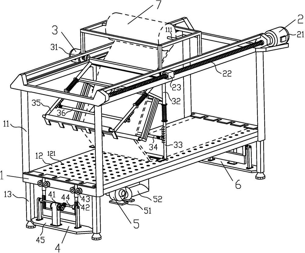
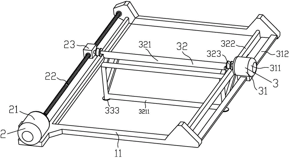
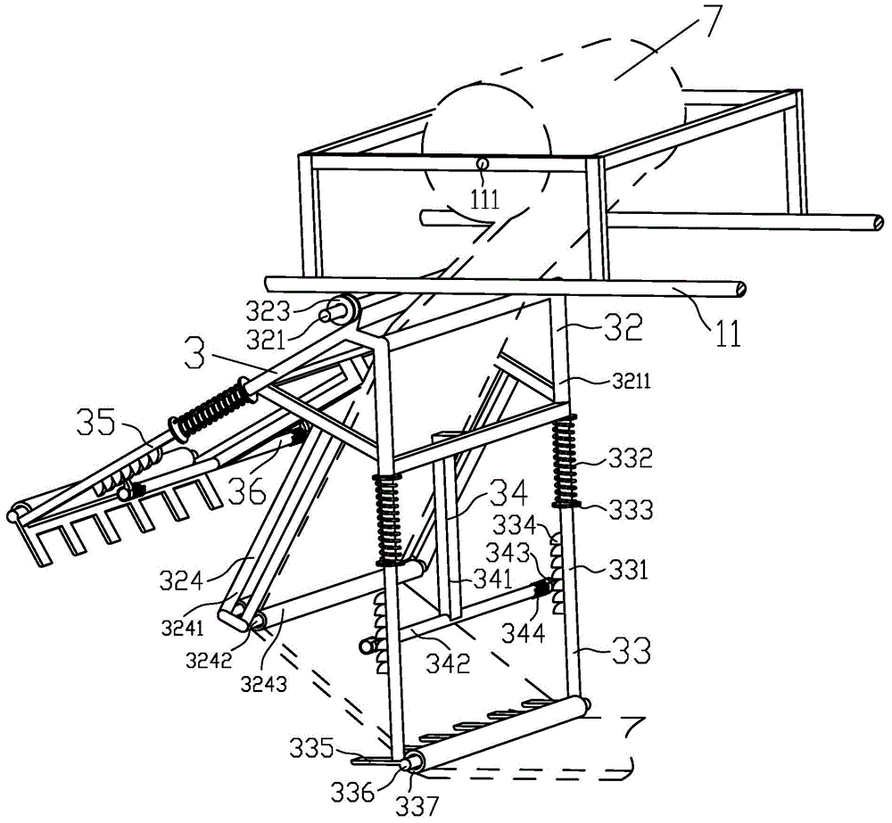

Image

  • Automatic spreading machine
  • Automatic spreading machine
  • Automatic spreading machine

Examples


Embodiment Construction

[0017] In order to make the technical means, creative features, objectives and effects achieved by the present invention easy to understand, the present invention will be further described below in conjunction with specific embodiments and illustrations.

[0018] Such as figure 1 and figure 2 As shown, an automatic cloth stretching machine is composed of a workbench 1, a cloth stretching device 2, a cloth spreading device 3, a left cloth pressing device 4, an adsorption device 5 and a right cloth pressing device 6. The workbench 1 is composed of a support frame 11, a spreading platform 12 and an adjustable table foot 13, the support frame 11 includes a support rod 111, and the support rod 111 is placed in the middle of the support frame 11, and The supporting frame 11 is connected by bearings, the spreading platform 12 is connected with the supporting frame 11 and placed under the supporting frame 11, the upper surface of the spreading platform 12 is evenly distributed with ...


PUM


Abstract

The invention discloses an automatic spreading machine which is composed of a workbench, a spreading device, a cloth laying device, a left cloth pressing device, an adsorption device and a right cloth pressing device. The workbench is composed of a supporting frame, a cloth laying platform and adjustable table legs. The spreading device is composed of a spreading motor, a lead screw and a movable sliding block. The cloth laying device is composed of a cloth laying driving device, a spreading connecting frame, a right cloth laying ascending mechanism, a right self-locking mechanism, a left cloth laying ascending mechanism and a left self-locking mechanism. The left cloth pressing device is composed of a cloth pressing driving device, a lifting mechanism, a pressing rod guide device, a cloth pressing transmission device and a cloth pressing supporting plate. The adsorption device is composed of an adsorption air pump and an air pipe. Cloth can be pulled out and flatly laid on the cloth laying platform with all the layers closely attached, and no wrinkle exists. Every time one layer of cloth is laid, cloth spreading and laying can be carried out in a reciprocating mode without breaking the cloth. According to the automatic spreading machine, manpower is saved, and cloth laying efficiency and quality are improved.

Description

technical field [0001] The invention relates to a cloth spreading machine, in particular to a novel automatic cloth spreading machine. Background technique [0002] China is a big garment production country, and the competition in the garment manufacturing industry is particularly fierce. How to systematically control the quality, cost and efficiency of finished products has become extremely important. Enterprises cut and process a large number of fabrics every day. The first step is to pull the fabric. The rolls of fabric are rolled out layer by layer to the cutting table. key factor. At present, small and medium-sized enterprises widely use manual pulling materials. First, the labor intensity is high, and workers need to walk dozens of kilometers back and forth on the production line every day; second, multiple workers are required to work together, which directly results in high labor costs; the biggest problem is production efficiency. Low, due to the limitations of pe...

Claims


Application Information

Patent Timeline
IPC IPC(8): B65H47/00B65H16/00B65H23/00
Inventor 刘万云刘琼李龙王成军荣莉
Owner ANHUI UNIV OF SCI & TECH
Why Eureka
Eureka Blog
Learn More