
Type-C socket connector

A socket connector, integrated technology, applied in the direction of connection, connecting device parts, contact parts, etc., can solve the problems of reduced strength of inserted components, accumulation of tolerances in three-layer structure, and reduced product reliability, etc., to reduce the number of assemblies, The effect of reducing tolerance accumulation and optimizing product structure

Inactive Publication Date: 2015-08-26
ALL BEST ELECTRONICS TECH CO LTD
View PDF0 Cites 0 Cited by
  • Summary
  • Abstract
  • Description
  • Claims
  • Application Information

AI Technical Summary

Problems solved by technology

[0004] In the existing USB Type-C socket connector, the insertion component is composed of an upper insertion component, a middle insertion component and a lower insertion component, wherein the upper insertion component is provided with an upper row of conductive terminals, the middle insertion component is provided with a central shielding piece, and the lower The plug-in component is equipped with a lower row of conductive terminals, thus forming a three-layer structure of the upper row of conductive terminals, the central shield and the lower row of conductive terminals. Cause tolerance accumulation, poor structural stability, and reduce product reliability

Method used


Image

  • Type-C socket connector
  • Type-C socket connector
  • Type-C socket connector

Examples


Embodiment Construction

[0031] In order to make the object, technical solution and advantages of the present invention clearer, the present invention will be further described in detail below in conjunction with the accompanying drawings. It is only stated here that the words for directions such as up, down, left, right, front, back, inside, and outside that appear or will appear in the text of the present invention are only based on the accompanying drawings of the present invention, and are not specific to the present invention. limited.

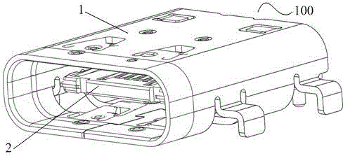
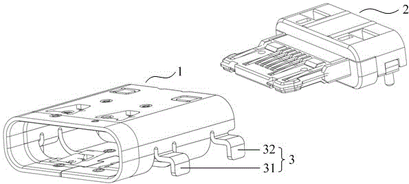
[0032] The present invention provides various implementations of a Type-C receptacle connector 100, which is used for mating with a plug connector.

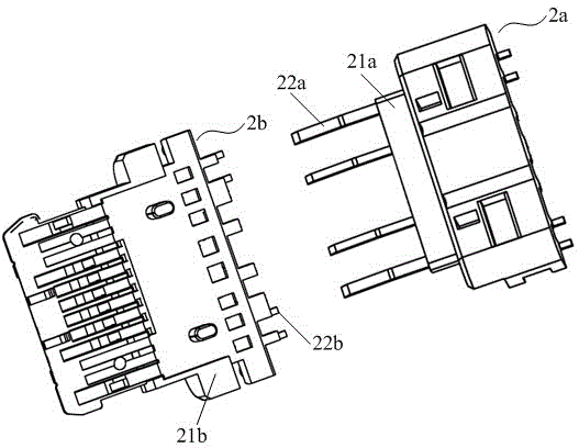
[0033] Such as Figure 1~Figure 3 As shown, the Type-C receptacle connector 100 includes a housing 1 and an insertion component 2 , and the housing 1 covers the outside of the insertion component 2 for shielding electromagnetic interference. The insert assembly 2 includes an upper insert assembly 2a and a lower in...


PUM


Abstract

The invention discloses a Type-C socket connector. The Type-C socket connector comprises a shell and plug-in assemblies, wherein the plug-in assemblies comprise an upper plug-in assembly and a lower plug-in assembly, the upper plug-in assembly comprises an upper insulating body and an upper row of conducting terminals which are integrally formed with the upper insulating body, and the lower plug-in assembly comprises a lower insulating body, metal shielding sheets and a lower row of conducting terminals which are integrally formed with the lower insulating body; notches for playing a clamping hook effect when being matched with a butting plug connector are formed in two sides of each metal shielding sheet; twelve grooves are formed in each insulating body, and at least four terminals are arranged on each row of conducting terminals; the metal shielding sheets are integrally formed with any two terminals in the lower row of conducting terminals, and the metal shielding sheets are raised downwards to form platy grounding parts. By adopting the Type-C socket connector, the assembling amount of components is reduced, the tolerance accumulation is reduced, the component strength of the lower plug-in assembly is effectively enhanced, and the amount of the conducting terminals is greatly reduced under the condition of guaranteeing electric quantity and stable information transmission.

Description

technical field [0001] The invention relates to the technical field of connectors, in particular to a Type-C socket connector. Background technique [0002] With the rapid development of science and technology in the electronics industry, the volume of electronic products is developing along the trend of becoming thinner and shorter, which requires the components of electronic products to be smaller and smaller, and the connector industry is the first to bear the brunt . [0003] Due to the requirement for a smaller size of the new generation of USB Type-C connectors, this leads to better mechanical performance requirements and more difficult product design. In order to face thinner and thinner equipment and ensure the reliability of product structure, major manufacturers have launched corresponding structural designs. [0004] In the existing USB Type-C socket connector, the insertion component is composed of an upper insertion component, a middle insertion component and ...

Claims


Application Information

Patent Timeline
Patent Type & Authority Applications(China)
IPC IPC(8): H01R13/514H01R13/6585H01R13/627H01R13/26H01R12/71
Inventor 彭易平翟重阳张安定程正云
Owner ALL BEST ELECTRONICS TECH CO LTD
Learn More