
Handle assembly

a technology for assembling parts and handles, applied in the direction of instruments, mechanical control devices, reels, etc., can solve the problems of insufficient strength of the mount part of the arm body, and achieve the effect of enhancing the strength of the part mounted to the handle shaft and enhancing the aesthetic appearance of the handle arm

Active Publication Date: 2016-03-31
SHIMANO COMPONENTS MALAYSIA
View PDF0 Cites 0 Cited by
  • Summary
  • Abstract
  • Description
  • Claims
  • Application Information

AI Technical Summary

Benefits of technology

The present invention aims to strengthen a component mounted on a handle shaft. The technical effect of this invention is to make the handle assembly more durable and resistant to damage.

Problems solved by technology

In other words, the strength of the mount part of the arm body may not be secured sufficiently when the mount part is mounted to the handle shaft, as the mount part is made of lightweight synthetic resin.

Method used


Image

  • Handle assembly
  • Handle assembly
  • Handle assembly

Examples


Embodiment Construction

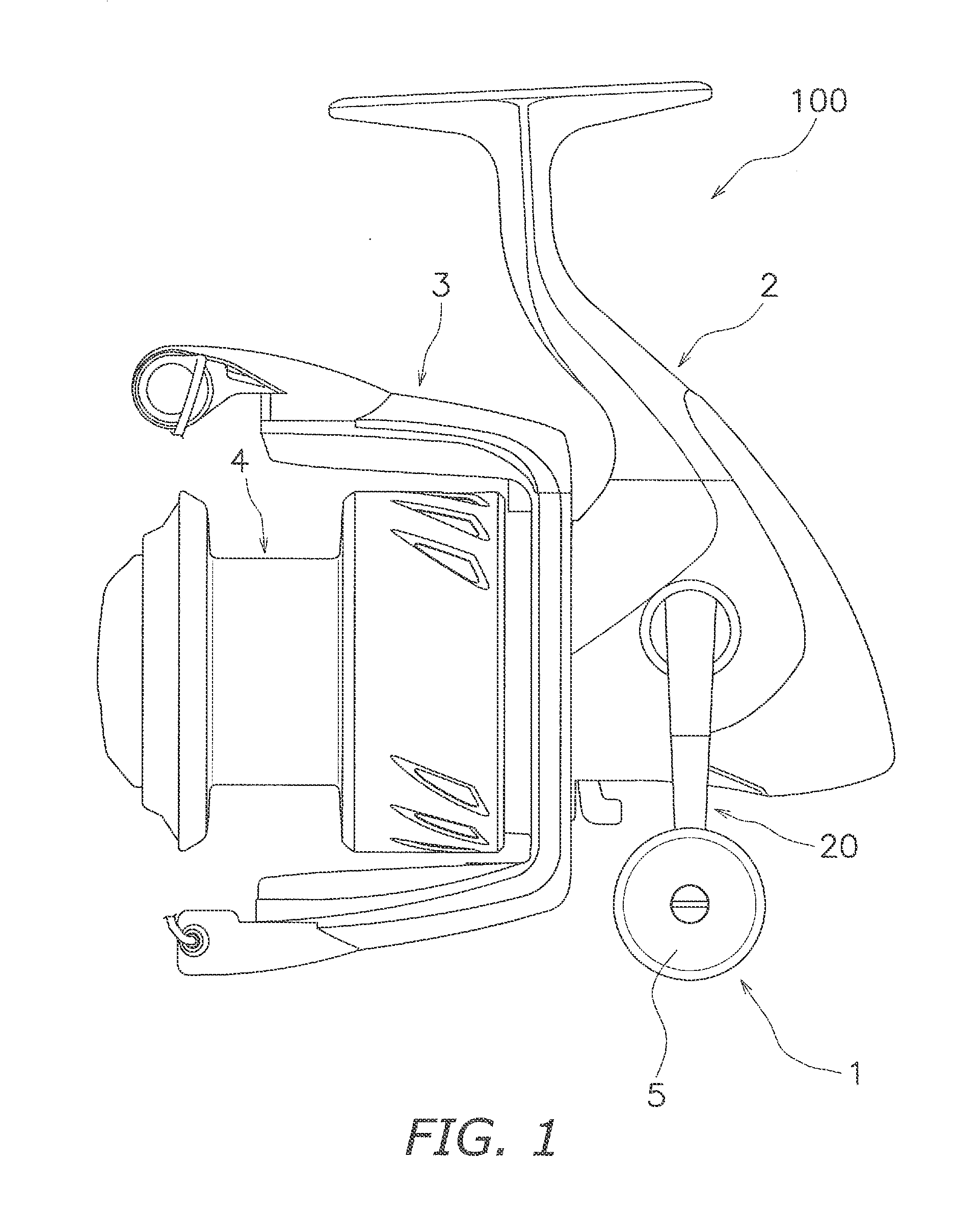
[0027]In FIG. 1, a spinning reel 100 according to a preferred embodiment of the present invention is capable of reeling out (casting) a fishing tine in the forward direction (leftward in FIG. 1).

[0028]The spinning reel 100 includes a handle assembly 1, a reel unit 2 supporting the handle assembly 1 in a rotatable state, a rotor 3 and a spool 4.

[0029]The handle assembly 1 is configured to rotate the rotor 3 and move the spool 4 back and forth. The handle assembly 1 will be described below in detail.

[0030]The rotor 3 is rotatably supported at the front of the reel unit 2. The rotor 3 is herein configured to be rotated when rotation of the handle assembly 1 is transmitted to the rotor 3 through a rotor drive mechanism (not shown in the drawings). It should be noted that the rotor drive mechanism is configured to be driven through a handle shaft 10 to which the handle assembly 1 is coupled.

[0031]The spool 4 is configured to wind the fishing line onto the outer peripheral surface thereof...


PUM


Abstract

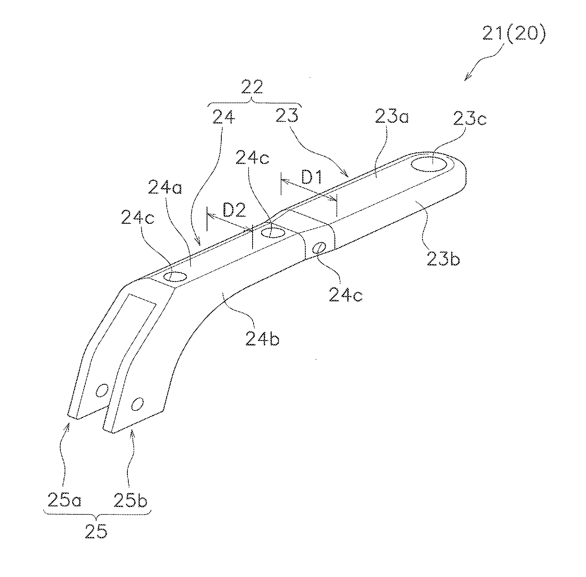
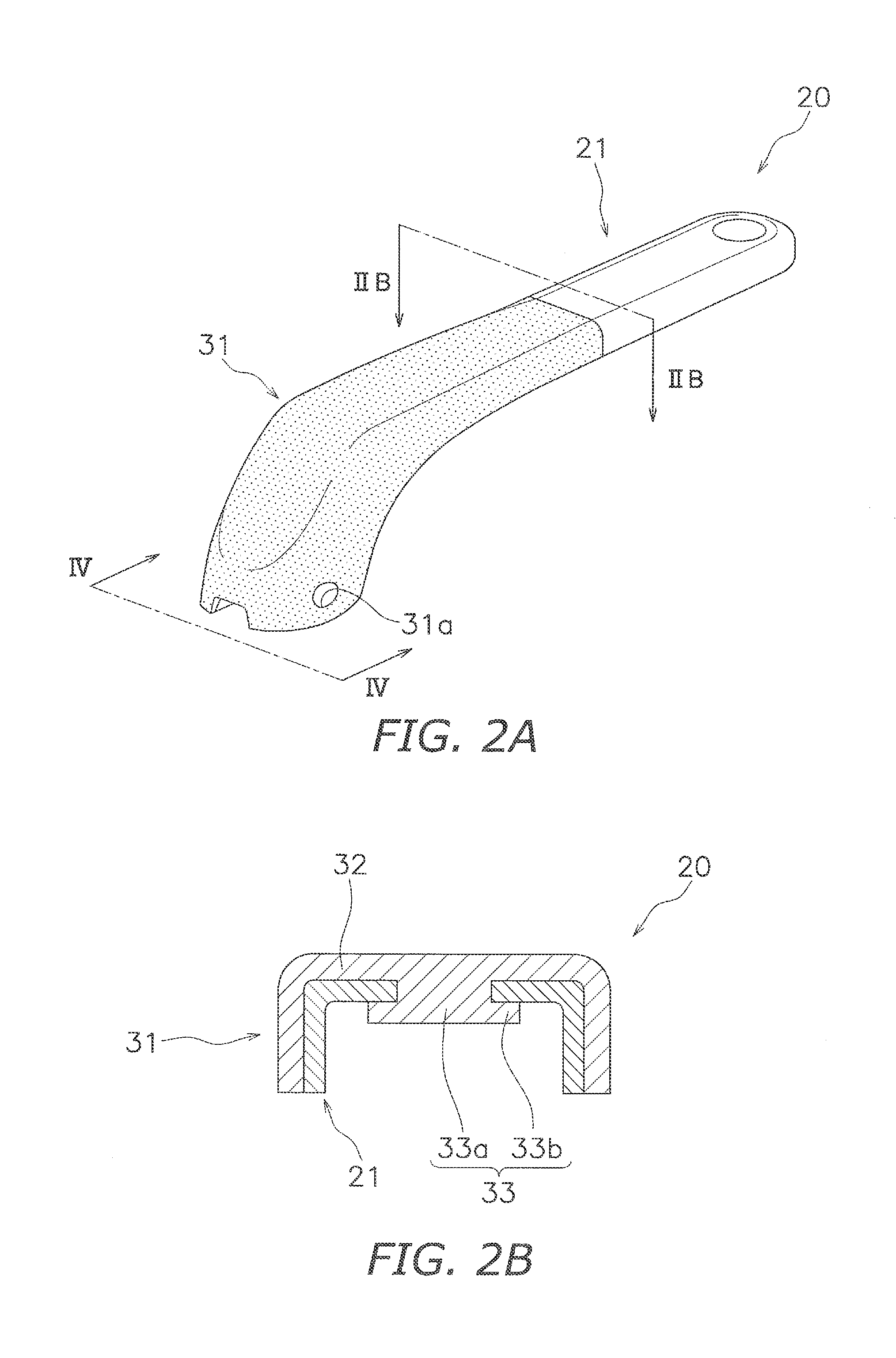
A present handle assembly is mounted to a handle shaft of a fishing reel. The handle assembly includes a handle arm and a handle knob. The handle arm is mounted to the handle shaft. The handle knob is mounted to the handle arm. The handle arm herein includes an arm body made of metal and a resin portion. The metallic arm body has a mount part and an arm part. The mount part is mounted to the handle shaft. The arm part is integrally formed with the mount part. The resin portion covers the mount part and at least a part of the arm part.

Description

CROSS-REFERENCE TO RELATED APPLICATIONS[0001]This application claims priority to Japanese Patent Application No. 2014-196347 filed on Sep. 26, 2014, the entirety of which is hereby incorporated by reference in its entirety.BACKGROUND[0002]1. Field of the Invention[0003]The present invention relates to a handle assembly, particularly to a handle assembly mounted to a handle shaft of a fishing reel.[0004]2. Background Information[0005]A handle assembly to be mounted to a handle shaft of a fishing reel has been disclosed as a conventional technology (see Japan Examined Utility Model Registration No. S52-008716). The handle assembly includes a handle arm and a handle knob mounted to the handle arm. The handle arm has an arm body and a reinforcement member (a box-like member) made of metal. The arm body is made of lightweight synthetic resin. The metallic reinforcement member is embedded in the middle of the arm body in order to reliably achieve stiffness required for the arm body. Furth...

Claims


Application Information

Patent Timeline
Patent Type & Authority Applications(United States)
IPC IPC(8): A01K89/00
CPCA01K89/006A01K89/00G05G1/10
Inventor GOH, MIANG, CHINLEE, WEN, YINLOH, HWEE, YUN
Owner SHIMANO COMPONENTS MALAYSIA
Learn More