Shift register unit, driving method thereof, gate driving circuit and display device

A shift register, driving signal technology, applied in static memory, digital memory information, instruments, etc., can solve the problem of insufficient anti-ESD (electrostatic discharge) capability of the circuit, large area occupied by the gate drive circuit, and occupied by the gate drive circuit. Large area and other problems, to improve the anti-ESD ability, improve the screen ratio, improve the effect of anti-ESD

Active Publication Date: 2017-04-05
HEFEI BOE OPTOELECTRONICS TECH +1
View PDF6 Cites 0 Cited by
  • Summary
  • Abstract
  • Description
  • Claims
  • Application Information

AI Technical Summary

Problems solved by technology

[0004] Since each shift register unit can only drive one row of gate lines to turn on and off, in the display panel, more shift register units need to be prepared to drive multiple rows of gate lines to turn on and off; in this case, it is necessary to The number of thin film transistors prepared on the array substrate is large, so the gate drive circuit will occupy a large area, which is not conducive to the realization of narrow borders.
In order to achieve a narrow frame, it is necessary to adopt a technical solution of double-sided driving (that is, to input a driving signal to the gate line at both ends of the gate line at the same time), but the use of double-sided drive will cause high temperature jitter, interlaced display and other defects.
In addition, the area occupied by the gate drive circuit is relatively large, and the wiring space of the protection circuit will be limited, so that the circuit's anti-ESD (electrostatic discharge) capability will be insufficient.

Method used


Image

  • Shift register unit, driving method thereof, gate driving circuit and display device
  • Shift register unit, driving method thereof, gate driving circuit and display device
  • Shift register unit, driving method thereof, gate driving circuit and display device

Examples


Embodiment Construction

[0033] Specific embodiments of the present invention will be described in detail below in conjunction with the accompanying drawings. It should be understood that the specific embodiments described here are only used to illustrate and explain the present invention, and are not intended to limit the present invention.

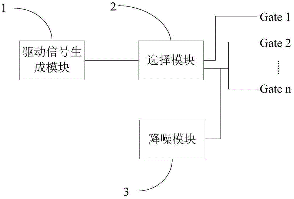
[0034] The present invention provides an implementation manner of a shift register unit, figure 1 A schematic diagram of a shift register unit provided in an embodiment of the present invention. Such as figure 1 As shown, in this embodiment, the shift register unit includes a driving signal generation module 1 and a selection module 2, wherein the driving signal generation module 1 is used to generate a driving signal for driving the gate line to be turned on, and the driving signal The duration is equal to the time required for scanning n rows of gate lines; said n≥2; the selection module 2 is connected to the input end of n rows of gate lines, and is used to...


PUM


Abstract

The invention relates to a shift register unit, a driving method thereof, a gate driving circuit and a display device. The shift register unit includes: a driving signal generating module, the driving signal generating module is used to generate a driving signal for driving the gate lines to be turned on, and the duration of the driving signal is equal to the time required for scanning n rows of gate lines; Said n≥2; a selection module, the selection module is connected to the input end of n rows of gate lines, and is used to sequentially gate the drive signal generation module with n rows of gate lines, and sequentially input the generated drive signals The n rows of gate lines. The above-mentioned shift register unit can reduce the area occupied by the gate drive circuit, thereby helping to realize narrow borders, increase the area of ​​the effective display area of ​​the display device, and increase the screen ratio of the display device; at the same time, it can also provide protection circuits. The arrangement provides enough space, which can improve the anti-ESD ability of the circuit.

Description

technical field [0001] The present invention relates to the field of display technology, in particular to a shift register unit, a driving method thereof, a gate driving circuit and a display device. Background technique [0002] In recent years, the development of displays has shown a trend of high integration and low cost. One of the very important technologies is the realization of mass production of shift register (English: Gate Driver on Array, abbreviation: GOA). The gate drive circuit is integrated on the array substrate of the display panel by using the shift register technology, so that the gate drive integrated circuit part can be saved, so as to reduce the product cost in terms of material cost and manufacturing process. [0003] The gate drive circuit using shift register technology includes several shift register units, and each shift register unit contains several thin film transistors (Thin Film Transistor, hereinafter referred to as TFT), wherein each shift ...

Claims


Application Information

Patent Timeline
Patent Type & Authority Patents(China)
IPC IPC(8): G09G3/20G11C19/28
CPCG09G3/20G09G2310/0218G09G2300/0426G09G2310/0286G11C19/28G09G3/2092G09G2300/0814G09G2310/08G09G2330/04
Inventor 周晓亮王洪伟余飞蒋磊
Owner HEFEI BOE OPTOELECTRONICS TECH
Why Eureka
Try Eureka