
Production method of flat plate type VIP with groove and refrigerator applying flat plate type VIP

A production method and technology for refrigerating cabinets, which are used in household refrigeration devices, applications, household appliances, etc., can solve problems such as affecting energy-saving effect and product quality, low thermal conductivity of aluminized film, and increased thermal conductivity, and achieve stable quality. Control, expansion and long life, high tensile strength effect

Inactive Publication Date: 2015-08-26
CHANGZHOU SANYOU DIOR INSULATION MATERIALS MFG
View PDF9 Cites 6 Cited by
  • Summary
  • Abstract
  • Description
  • Claims
  • Application Information

AI Technical Summary

Problems solved by technology

[0011] The deficiencies of the above-mentioned prior art are: the fiber diameter is relatively thick, the length is long (6-13um in diameter, 4-20mm in length), and the fiber is relatively hard; In the actual production or use process, the fiber is easy to pierce the aluminized film; therefore, when producing VIP, the outsourcing sealing film generally does not use aluminized film; currently, aluminum foil composite film is mostly used to produce VIP , to overcome the above problems; and this brings new problems, because the aluminum foil composite film contains pure aluminum layer (AL) and aluminum plating layer (VMPET), and the aluminum layer is thick (generally about 7um), resulting in VIP In the actual application process, there will be a relatively serious thermal bridge effect, which will inevitably lead to an increase in the overall thermal conductivity of VIP, thereby affecting energy saving effects and product quality.
[0013] The aluminized film contains an aluminized layer (VMPET) instead of a pure aluminum layer (AL), so the thermal conductivity of the aluminized film is much lower than that of the aluminum foil composite film

Method used


Image

  • Production method of flat plate type VIP with groove and refrigerator applying flat plate type VIP
  • Production method of flat plate type VIP with groove and refrigerator applying flat plate type VIP
  • Production method of flat plate type VIP with groove and refrigerator applying flat plate type VIP

Examples


Embodiment 1

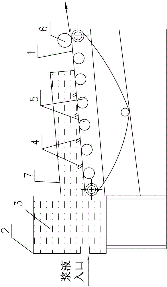
[0064] The production method of the vacuum heat insulation panel of this embodiment includes: putting the core material whose upper and lower sides are flat into the packaging film bag, and then putting it into the cavity of the vacuum device, and placing the core material on the upper side or the lower side of the packaging film bag. Place a compact on the side for pressing grooves or protrusions on the core material during vacuuming, then close the vacuuming device and implement vacuuming; wherein, during vacuuming, in the cavity , pressing the briquetting block or a pressing plate to one side of the packaging film bag (when applying pressure, the pressing plate is on the back of the briquetting block, or the pressing block and the pressing plate are respectively on the upper and lower sides of the packaging film bag), To press the groove or protrusion on the core material through the pressing block; when the vacuum is completed, the opening of the packaging film bag is heat-...

Embodiment 2

[0069] On the basis of Embodiment 1, the production method of the vacuum insulation panel of this embodiment has the following modifications:

[0070]The production method of the vacuum heat insulation panel in this embodiment includes: putting the core material whose upper and lower sides are flat into the packaging film bag, and then putting it into the cavity of the vacuum pumping device for vacuuming, and then putting the core material of the packaging film bag The opening is heat-sealed; then, place a briquetting block for pressing a groove or a protrusion on the core material when vacuuming on the upper side or the lower side of the packaging film bag, and place the briquetting block or a pressing plate toward the One side of the packaging film bag is pressed to press the groove or protrusion on the core material through the pressing block; then, the vacuum insulation panel is taken out from the cavity, and then Manual folding, that is, the finished product.

[0071] As...

Embodiment 3

[0073] The packaging film for vacuum insulation panels of the above-mentioned embodiment 1 or 2 has the characteristics of a large temperature resistance range and flame retardancy, and includes: a protective layer, a gas barrier layer and a heat-welding layer, and the heat-sealing layer is an ETFE material layer, Its thickness is 15-95 μm.

[0074] As the protective layer, a coextruded stretched film (hereinafter referred to as a coextruded stretched film) obtained by sequentially laminating a nylon-based resin, an ethylene-vinyl alcohol copolymer, and a nylon-based resin is used. This co-extruded stretched film does not use an adhesive, but by co-extruding, a flexible nylon-based resin is laminated on both sides of the gas-barrier ethylene-vinyl alcohol copolymer to give it flexibility. and gas barrier properties.

[0075] As the gas barrier layer, a metal foil, a plastic film formed with a thin film layer of metal or metal oxide, or a combination of these can be used.

[...


PUM

PropertyMeasurementUnit
Thicknessaaaaaaaaaa
Fiber diameteraaaaaaaaaa
Lengthaaaaaaaaaa

Abstract

The invention provides a high-feasibility and simple-process production method of a flat plate type VIP (vacuum insulation panel) with a groove or a bulge in a single side. The production method comprises the following steps: a core material, of which the upper side surface and the lower side surface are planes, is placed in a packing film bag, and then is placed in a cavity of a vacuum device, a pressing block for forming a groove or a bulge in the core material through pressing in vacuum pumping is placed on the upper side surface or the lower side surface of the packing film bag, and then the vacuum device is closed and the vacuum pumping is carried out; in vacuum pumping, in the cavity, a pressing plate applies pressure to one side surface of the packing film bag to enable the groove or the bulge to be pressed on the core material through the pressing block; when the vacuum pumping is completed, an opening of the packing film bag is subjected to heat seal, and then the vacuum insulation plate is taken out of the cavity, so that the finished product is obtained.

Description

technical field [0001] The invention relates to a production method of a flat vacuum insulation panel (VIP) with grooves and a refrigeration cabinet using the VIP. Background technique [0002] Vacuum insulation panels (hereinafter referred to as VIP) are widely used in various thermal insulation fields. The shape of VIP is also changing according to actual production needs; it usually includes rectangular flat panels and special-shaped panels; rectangular flat panels are conventional products and are relatively easy to produce, while special-shaped panels It requires a special process. [0003] The production method of rectangular flat VIP is to put the core board into a pre-processed film bag with three sides and one opening, then vacuumize from the opening side, and finally heat seal the opening (that is, complete the sealing), At the same time, sealing edges are produced around the finished product, and then the surrounding sealing edges are artificially folded and fixe...

Claims


Application Information

Patent Timeline
IPC IPC(8): F16L59/02F16L59/065F25D23/00
CPCF16L59/065F25D23/00
Inventor 糜玥崎
Owner CHANGZHOU SANYOU DIOR INSULATION MATERIALS MFG
Learn More