
Member residual stress field prediction method based on limited test points

A technology of residual stress and test points, which is applied in the field of component residual stress field prediction, can solve problems such as large errors between prediction results and actual results, inability to represent residual stress fields, and difficulty in simulation and realization of residual stress prediction, so as to improve prediction accuracy , to ensure the effect of stress continuity

Inactive Publication Date: 2015-08-19
HUAZHONG UNIV OF SCI & TECH
View PDF6 Cites 6 Cited by
  • Summary
  • Abstract
  • Description
  • Claims
  • Application Information

AI Technical Summary

Problems solved by technology

The finite element simulation method is another method to know the distribution of the residual stress field of the component, but most of the current research is to simulate the distribution from the actual manufacturing process of the component, such as casting, cutting, welding, etc. The stress has changed accordingly, and the residual stress field cannot be characterized only by simulating the casting process. At the same time, due to the lack of a correct characterization method for the initial stress field of the blank, the error between the predicted result and the actual result is large. At the same time, for the component manufacturing process The residual stress prediction of components with complex or unknown manufacturing process is difficult to realize by simulation

Method used


Image

  • Member residual stress field prediction method based on limited test points
  • Member residual stress field prediction method based on limited test points
  • Member residual stress field prediction method based on limited test points

Examples


Embodiment Construction

[0020] In order to make the object, technical solution and advantages of the present invention clearer, the present invention will be further described in detail below in conjunction with the accompanying drawings and embodiments. It should be understood that the specific embodiments described here are only used to explain the present invention, not to limit the present invention. In addition, the technical features involved in the various embodiments of the present invention described below can be combined with each other as long as they do not constitute a conflict with each other.

[0021] The present invention is based on the residual stress field in the component, the displacement is continuous, and the assumption that the residual stress field is balanced at the time of research. In view of the measurable residual stress on the surface of the component, the finite element theory is used to solve the residual stress of the component based on the experimental test value. f...


PUM


Abstract

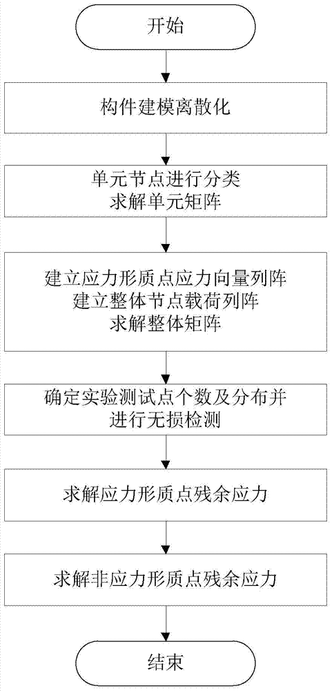
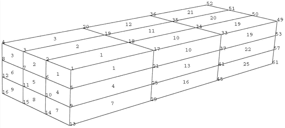
The invention discloses a member residual stress field prediction method based on limited test points. The method comprises the following steps: 1, carrying out structural discretization; 2, classifying unit nodes, establishing a displacement shape function matrix and a unit stress function matrix, and then solving a unit matrix; 3, according to the unit matrix, establishing a stress shape particle residual stress vector array and an integral node load array, and solving an integral matrix; 4, according to the rank of the integral matrix, determining the number, distribution and testing of experiment test points; 5, according to a tested residual stress experiment result as a residual stress boundary condition, solving all stress shape particle residual stress; and 6, according to the stress shape particle residual stress and the unit stress function matrix, solving non-stress shape particle residual stress so as to obtain a residual stress field of a member. According to the invention, the residual stress of the member can be accurately predicted without restrictions of the material and the structural shape of the member, and the method has obvious advantages especially in a manufacturing process of an unknown member and residual stress prediction of a complex member.

Description

technical field [0001] The invention belongs to the technical field of nondestructive testing, and more specifically relates to a method for predicting component residual stress fields based on limited test points. Background technique [0002] When an object is not subjected to external force, the internal stress system that maintains self-equilibrium is usually called residual stress. Various machining processes, such as cutting, casting, heat treatment, welding, assembly, etc., will produce residual stress to varying degrees, and residual stress has an impact on the static mechanical properties, stress corrosion performance, fatigue resistance, dimensional stability and service life of materials. How to accurately predict the internal residual stress field distribution of components is of great significance to the material and structural design of components, and has become the focus of general attention in recent years. [0003] At present, methods for obtaining compone...

Claims


Application Information

Patent Timeline
IPC IPC(8): G01L1/00
Inventor 毛宽民王凤云李斌
Owner HUAZHONG UNIV OF SCI & TECH
Learn More