
A structure for reducing internal force of tunnel lining structure and its construction method

A technology of structural internal force and construction method, which is applied in the construction of the structure, the structure that reduces the internal force of the tunnel lining structure, and the field of tunnel support design, can solve the problems of large internal force of the support structure, large surface settlement and deformation, etc., and achieve the support strength. The effect of weakening, reducing surface subsidence deformation, and reducing the amount of surface subsidence deformation

Active Publication Date: 2017-05-31
CCCC SECOND HIGHWAY CONSULTANTS CO LTD
View PDF7 Cites 0 Cited by
  • Summary
  • Abstract
  • Description
  • Claims
  • Application Information

AI Technical Summary

Problems solved by technology

[0003] In order to solve the above-mentioned problems in the prior art, the present invention provides a structure for reducing the internal force of the tunnel lining structure, which is simple in structure, convenient in construction, and effectively solves the problem of supporting tunnels (especially large-section tunnels) under complex geological conditions. The problem of excessive internal force of the structure and large deformation of the ground surface
[0004] The invention also provides a construction method for reducing the internal force of the tunnel lining structure. The method is simple and easy to operate, and effectively solves the problem of excessive internal force of the support structure of the tunnel (especially a large-section tunnel) and the problem of ground surface under complex geological conditions. Large problem of settlement deformation

Method used


Image

  • A structure for reducing internal force of tunnel lining structure and its construction method
  • A structure for reducing internal force of tunnel lining structure and its construction method
  • A structure for reducing internal force of tunnel lining structure and its construction method

Examples


Embodiment 1

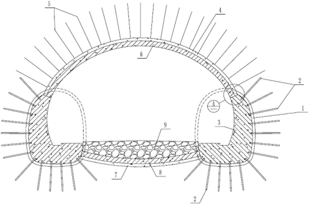
[0039] The structure of the structure for reducing the internal force of the tunnel lining structure provided by this embodiment is as follows figure 1 As shown, the structure at least includes the initial support of the pilot pit 1, the initial support of the arch 4, the initial support of the invert 7, the second arch lining 6, the second invert lining 8 and the invert backfill 9. The initial arch support includes at least an arch frame 10, and anchor rods 5 are evenly distributed on the arch initial support. The initial support of the pilot pit 1 includes the initial support of the left pilot pit and the initial support of the right pilot pit. Small conduits 2 are evenly provided on the side walls of the left pilot pit initial support and the right pilot pit initial support in contact with the surrounding rock. The left side wall lining is provided on the inner side of the side wall where the initial support of the left pilot pit is in contact with the surrounding rock, and ...

Embodiment 2

[0043] The structure of the structure for reducing the internal force of the tunnel lining structure provided by this embodiment is as follows figure 1 As shown, the structure includes at least the initial support 1 of the pilot pit, the initial support 4 of the arch, the initial support 7 of the invert, the second lining of the arch 6, the second lining of the invert 8 and the backfill 9 of the invert. The initial arch support includes at least an arch frame 10, and anchor rods 5 are evenly distributed on the arch initial support. The initial support of the pilot pit 1 includes the initial support of the left pilot pit and the initial support of the right pilot pit. Small conduits 2 are evenly provided on the side walls of the left pilot pit initial support and the right pilot pit initial support in contact with the surrounding rock. The left side wall lining is provided on the inner side of the side wall where the initial support of the left pilot pit is in contact with the s...

Embodiment 3

[0062] 1) Excavate the pilot pits on both sides of the tunnel, and implement the initial support of the left pilot pit and the initial support of the right pilot pit. Small pipes are uniformly applied on the side walls where the initial support of the left pilot pit and the initial support of the right pilot pit are in contact with the surrounding rock, and the surrounding rock is reinforced by grouting through the small pipes on both sides. The small conduit should be a seamless steel tube with a diameter of 30-50mm and a length of 25-400mm. The grouting material can be cement single-liquid slurry, cement-water glass double-liquid slurry, etc. according to the geological conditions. The selection, proportion and grouting pressure of grouting materials should be determined by experiments.

[0063] 2) Construct the left thick side wall lining on the inner side of the side wall where the initial support of the left pilot pit is in contact with the surrounding rock, and construct th...


PUM


Abstract

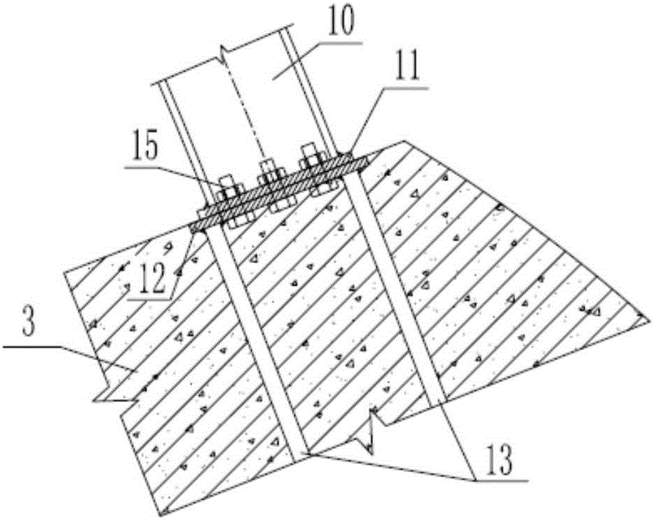
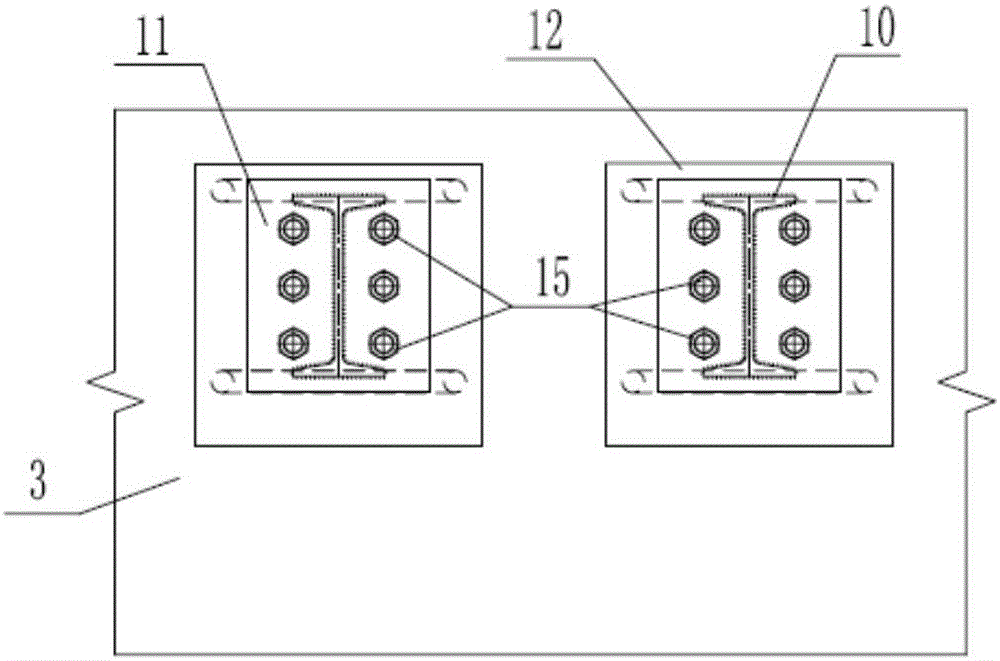
The invention provides a tunnel lining structure internal force reducing structure and a construction method thereof. The structure comprises two-side guide pit initial supports, an arch initial support, an invert initial support and an invert backfill. The two-side guide pit initial supports are provided with small guide tubes and rear wall liners; two steel plates and anchoring steel bars are pre-embedded in two-side thick wall liners; two steel base plates are fixed to the end surfaces of two ends of an arch frame and are connected to the pre-embedded steel plates respectively. The method includes excavating the guide pits of two sides of a tunnel; arranging the two-side guide pit initial supports and the small guide tubes, and injecting slurry to reinforce the surrounding rock; arranging the two-side concrete thick wall liners; excavating the arch soil, arranging the arch initial support, and connecting the arch frame with the thick wall liners; arranging an arch secondary support, excavating the lower soil, and arranging the invert initial support, an invert secondary liner and the invert backfill. The structure and constructing method are simple, and the problem that the tunnel supporting structure internal force is excessively large is solved.

Description

Technical field [0001] The invention relates to the technical field of tunnel excavation and support, in particular to a structure for reducing the internal force of the tunnel lining structure, and also to a construction method for reducing the internal force of the tunnel lining structure, which is suitable for tunnels under complex geological conditions (especially It is a tunnel support design with large overlying load and strict stratum settlement control. Background technique [0002] In recent years, with the rapid development of highways, railways and urban construction in my country, more and more large-section and super-large-section tunnels under various complex geological conditions have been constructed. Due to the large span and small height-span ratio, the surrounding rock loose load height of the super-large section tunnel is very high, and the surrounding rock pressure is very high, which leads to the positive bending moment of the arch of the supporting structur...

Claims


Application Information

Patent Timeline
Patent Type & Authority Patents(China)
IPC IPC(8): E21D11/10E21D11/22E21D20/00
CPCE21D11/105E21D11/22E21D20/00
Inventor 毛红飞郭小红刘继国李昕
Owner CCCC SECOND HIGHWAY CONSULTANTS CO LTD
Learn More