
Method for blanking cylindrical formwork at joint part of V-shaped cylinder

A column and formwork technology, applied in the field of cylindrical formwork blanking at "V"-shaped cylindrical joints, can solve the problems of high cost of steel formwork and transportation, high technical requirements for construction, and impact on project quality, and achieves flexible cutting and easy quality. Guaranteed, the effect of low equipment investment

Active Publication Date: 2015-08-19
CHINA METALLURGICAL CONSTR ENG GRP
View PDF5 Cites 2 Cited by
  • Summary
  • Abstract
  • Description
  • Claims
  • Application Information

AI Technical Summary

Problems solved by technology

However, the formwork construction of the cast-in-place reinforced concrete "V"-shaped cylindrical joints has become a major difficulty. The construction technology requires high and difficult construction, which has an important impact on the quality of the project.
Generally, shaped steel molds or shaped FRP molds are usually used for the construction of "V"-shaped cylindrical joints. However, due to the disadvantages of steel formwork, such as high cost and transportation cost, heavy weight, cumbersome disassembly and assembly, and manpower occupation, it has become a relatively complicated process in the construction process. ;In recent years, although the novel fiberglass formwork has solved the limitations of heavy weight and manpower, it has disadvantages such as easy formation of air bubbles, large arc deformation, and easy damage. Moreover, these two forms are suitable for multi-section and special-shaped structures. have great limitations

Method used


Image

  • Method for blanking cylindrical formwork at joint part of V-shaped cylinder
  • Method for blanking cylindrical formwork at joint part of V-shaped cylinder
  • Method for blanking cylindrical formwork at joint part of V-shaped cylinder

Examples


Embodiment

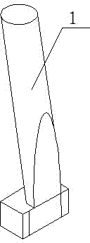
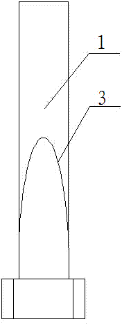
[0033] Example: see Figure 1-Figure 5 , the present embodiment is thick with 18mm, the long semicircular arc wooden formwork of 3m as cylindrical formwork.

[0034] A method for blanking a cylindrical formwork at a "V"-shaped cylindrical node position, comprising the following steps:

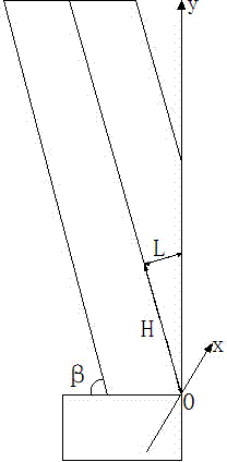
[0035] S1: The cylindrical formwork at the "V"-shaped cylindrical node part is composed of two cylindrical formworks (the cylindrical formwork is hollow), the lower half of the two cylindrical formworks are combined into one, and the joint part of the bottom of the two cylindrical formworks The contour is a semi-ellipse; use BIM technology to establish a three-dimensional view of the "V"-shaped cylinder, cut the intersecting line for data analysis, and obtain the cutting contour line of the "V"-shaped cylindrical formwork shown in the form of a semi-ellipse.

[0036] S2: Carry out cutting on the cylindrical formwork, the method that the contour line of the cutting surface is a semi-ellipse is ...


PUM


Abstract

The invention relates to a method for blanking a cylindrical formwork at a joint part of a V-shaped cylinder, which comprises the steps of 1, establishing a coordinate system and determining a mathematical expression of a cutting contour line; 2, determining semi-elliptical cutting points at a lower half portion of the cylindrical formwork, and determining a cutting point at the lower half portion of the cylindrical formwork according to the mathematical expression of the cutting contour line and a value range of a horizontal coordinate of the cutting point, wherein an H-value and an L-value are acquired correspondingly every time when a value is assigned to the horizontal coordinate of the cutting point; and 3, determining a series of cutting points according to the method provided in the step 2, and carrying out cutting along the cutting point in sequence so as to realize blanking of the cylindrical formwork at the joint part of the V-shaped cylinder. The method provided by the invention can accurately control the precision of the cutting contour line, thereby effectively avoiding deviation at the joint part of two cylindrical formworks.

Description

technical field [0001] The invention relates to a method for blanking a cylindrical formwork at a node position of a "V"-shaped cylinder. Background technique [0002] With the continuous improvement of construction technology, the architectural shapes become more novel and diversified, and the cast-in-place reinforced concrete "V"-shaped cylindrical structures are more and more used in engineering. However, the formwork construction of cast-in-place reinforced concrete "V"-shaped cylindrical joints has become a major difficulty. The construction technology requires high and difficult construction, which has an important impact on the quality of the project. Generally, shaped steel molds or shaped FRP molds are usually used for the construction of "V"-shaped cylindrical joints. However, due to the disadvantages of steel formwork, such as high cost and transportation cost, heavy weight, cumbersome disassembly and assembly, and manpower occupation, it has become a relatively c...

Claims


Application Information

Patent Timeline
Patent Type & Authority Applications(China)
IPC IPC(8): B23D15/06E04G13/02
Inventor 刘义权孙慧星张建东
Owner CHINA METALLURGICAL CONSTR ENG GRP
Learn More