Eureka AIR delivers breakthrough ideas for toughest innovation challenges, trusted by R&D personnel around the world.

Glass fiber furnace kiln waste gas desulfurization device with turbo-charging turbulator and process

A turbocharging and glass fiber technology, applied in chemical instruments and methods, dispersed particle separation, separation methods, etc., can solve problems such as low efficiency, failure to meet the requirements of new emission standards, and poor desulfurization and defluorination effects. To achieve the effect of improving efficiency, saving energy, and good absorption

Inactive Publication Date: 2015-08-19
刘启杰
View PDF7 Cites 5 Cited by
  • Summary
  • Abstract
  • Description
  • Claims
  • Application Information

AI Technical Summary

Problems solved by technology

In response to this situation, the traditional tail gas desulfurization and defluorination equipment in the past can no longer adapt to the requirements of the new situation. As the traditional tail gas treatment equipment in the past, it is simply spraying the tail gas / or flue gas with water, or using water Add alkali solution to spray tail gas and / or flue gas
For the existing known technology and the current situation, there are deficiencies, defects and drawbacks such as poor desulfurization and defluorination effect, low efficiency, and failure to meet the requirements of the new emission standards.

Method used


Image

  • Glass fiber furnace kiln waste gas desulfurization device with turbo-charging turbulator and process
  • Glass fiber furnace kiln waste gas desulfurization device with turbo-charging turbulator and process

Examples


Embodiment Construction

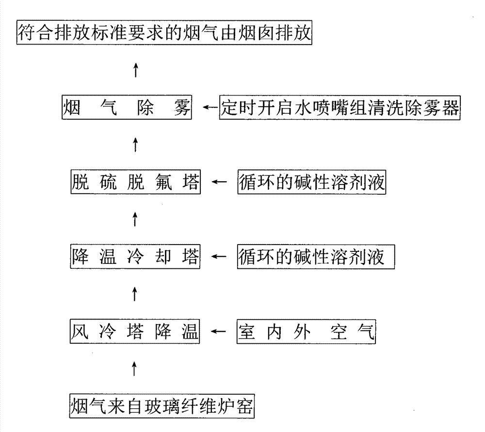
[0039] The present invention will be described in detail below in conjunction with the accompanying drawings. As attached to the manual figure 1 , 2 Shown:

[0040] A glass fiber kiln exhaust gas desulfurization device equipped with a turbocharged turbulator, comprising a kiln flue gas pipe 1, a supplementary air valve 2, an air cooling tower 3, a cooling tower 4, and an atomizing nozzle group in the cooling tower 4 5. Desulfurization tower 6, desulfurization nozzle group 7 in desulfurization tower 6, water nozzle group 8 in desulfurization tower 6, turbocharged turbulence device 18 in desulfurization tower 6, receiving tank 9 and circulation tank 10 in desulfurization tower 6, The agitator 11 in the circulation tank 10, the desulfurization pump 12, the atomization pump 13, the auxiliary tower flue 14, the induced draft fan 15, the chimney 16, and the blowdown valve 17;

[0041] In the glass fiber kiln waste gas desulfurization device provided with a turbocharged turbulator...


PUM


Abstract

The invention discloses a glass fiber furnace kiln waste gas desulfurization device with a turbo-charging turbulator, and a process, belonging to the technical field of environment protection. According to the glass fiber furnace kiln waste gas desulfurization device, a furnace kiln fume tube and an air supplement valve, an air cooling tower and a cooling tower, the cooling tower and a desulfurization tower are fixed by using pipelines; the furnace kiln fume tube is fixed with the air cooling tower, and the cooling tower is fixed with an atomization nozzle group; the cooling tower and a receiving tank are fixed with a pipeline inserting into a circulation tank; the inner wall of the desulfurization tower is fixed with a water nozzle group, a desulfurization nozzle group, the turbo-charging turbulator and the receiving tank in sequence; a stirrer is arranged inside the circulation tank; the circulation tank is fixed with a desulfurization pump as well as an atomization pump by pipelines; the desulfurization pump is fixed with the desulfurization nozzle group by a pipeline, and the atomization is fixed with and the atomization nozzle group by a pipeline; the desulfurization tower is fixed with a secondary tower flue by a pipeline, the secondary tower flue is fixed with a draft fan by a pipeline, the draft fan is fixed with a chimney by a pipeline, and the circulation tank is fixed with a blow-down valve by a pipeline. The process comprises the steps that fume is subjected to air cooling, temperature reduction, desulfurization, defluorination, demisting and discharge and the liquid is refluxed, the overall operation is organic, automatic and continuous, and thus sewage can be discharged in appropriate time. The glass fiber furnace kiln waste gas desulfurization device is applied to fume desulfurization and defluorination. The device is smart and simple in process, and stable in effect.

Description

technical field [0001] The invention relates to a glass fiber kiln exhaust gas desulfurization device and process provided with a turbocharger turbulator, and relates to the technical field of environmental protection. Background technique [0002] At present, in the process of glass fiber production at home and abroad, the exhaust gas of glass fiber kiln contains a certain amount of harmful exhaust gas such as sulfur dioxide and hydrogen fluoride. Because sulfur dioxide and hydrogen fluoride gas have a great impact on human health and great damage to the environment , so the country has always been stricter in management, especially in recent years, it has put forward stricter and newer requirements for exhaust emissions containing the above-mentioned exhaust gases. In response to this situation, the traditional tail gas desulfurization and defluorination equipment in the past can no longer adapt to the requirements of the new situation. As the traditional tail gas treatmen...

Claims


Application Information

Patent Timeline
IPC IPC(8): B01D53/78B01D53/50B01D53/68
Inventor 刘启杰
Owner 刘启杰
Why Eureka
Eureka Blog
Learn More