Brushless motor assembly structure

A brushless motor and assembly structure technology, which is applied in the field of motor assembly structure and brushless motor assembly structure, can solve the problem of inability to use both integral and split types, screws are easily sucked into the surface of magnetic steel, hot-melt welding and fixing times High product rate and other issues, achieve the effect of reducing labor cost and raw material cost, improving assembly process, and good product stability

Inactive Publication Date: 2015-08-12
YUYAO ACTUATOR ELECTRIC MOTOR CO LTD
View PDF4 Cites 1 Cited by
  • Summary
  • Abstract
  • Description
  • Claims
  • Application Information

AI Technical Summary

Problems solved by technology

[0005] The purpose of the present invention is to address the prior art of the assembly structure of the above-mentioned brushless motor. There is a large surface jump after the magnetic ring is bonded, which leads to excessive vibration of the motor, or the crack of the magnetic ring due to the small air gap of the motor, and the Hall plate and stator assembly. The use of glue to fix the parts will increase the man-hours and reduce the production efficiency. The hot-melt welding fixation ...

Method used


Image

  • Brushless motor assembly structure
  • Brushless motor assembly structure
  • Brushless motor assembly structure

Examples


Embodiment Construction

[0041] The present invention will be further described below in conjunction with the accompanying drawings and specific embodiments, but not as a limitation of the present invention.

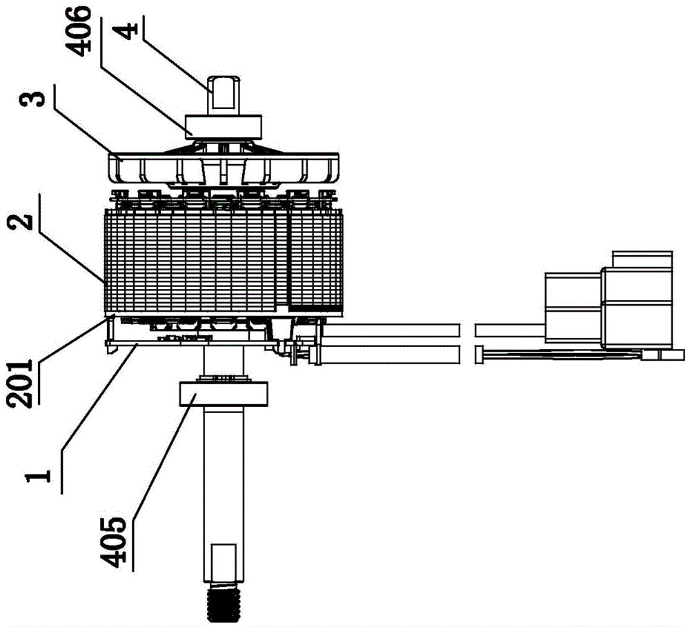
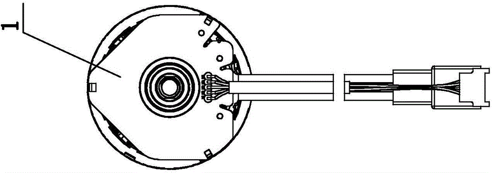
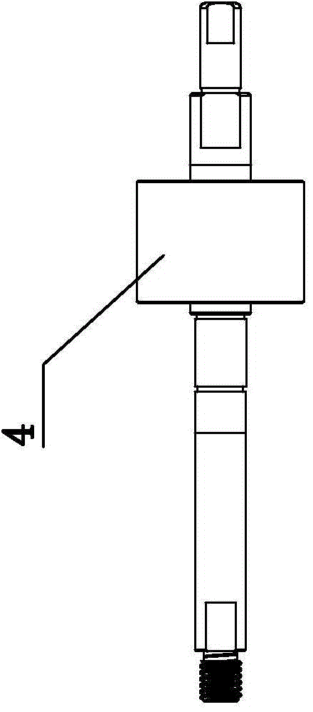
[0042] Such as Figure 1-1 to Figure 7-2 As shown, an assembly structure of a brushless motor includes a Hall plate 1, a stator assembly 2, an air blade 3 and a rotor assembly 4; the Hall plate 1 is arranged in front of the stator assembly 2, and the air blade 3 is arranged in the Behind the stator assembly 2, the fan blade 3 is fixedly connected to the stator assembly 2, and the rotor assembly 4 is rotationally connected to the stator assembly 2; the stator assembly 2 includes an insulating end plate 201, and the insulating end plate 201 is at the front end of the stator assembly 2, The rotor assembly 4 includes a rotor chip 401 and a magnetic ring 402. The rotor chip 401 is arranged in the magnetic ring 402. Eight arc-shaped grooves 403 are uniformly arranged on the outer edge of the rotor chi...


PUM

PropertyMeasurementUnit
Heightaaaaaaaaaa

Abstract

A brushless motor assembly structure belongs to the technical field of motor equipment assembly. The brushless motor assembly structure comprises a Hall plate, a stator assembly, and a rotor assembly. The stator assembly comprises an insulating end plate, and the Hall plate is fixed to the stator in a self-buckling way through the insulating end plate. The rotor assembly comprises a rotor chip and a magnetic ring. The outer edge of the rotor chip is uniformly provided with 4-12 arc grooves, the area between every two adjacent arc grooves is in clearance fit with a corresponding inner hole of the magnetic ring, 4-12 clearance sections are formed, and the clearance portions are filled with anaerobic glue water. The middle of each clearance section at the outer edge of the rotor chip is provided with a convex arc surface, the total number of the convex arc surfaces is 4-12, the height of the convex arc surfaces is 0.06 mm, and the convex arc surfaces are in tight fit with the corresponding inner holes of the magnetic ring. By adopting the brushless motor assembly structure of the invention, the following beneficial effects are achieved: the surface of the magnetic ring does not jump after bonding, the motor vibration is small, the air gap of a motor is normal, the magnetic ring does not crack, the Hall plate and the stator assembly are fixed in a plugging way, the production efficiency is improved, the defective rate is reduced, and the integrity of the structure is achieved.

Description

technical field [0001] The invention relates to an assembly structure of a motor, in particular to an assembly structure of a brushless motor, and belongs to the technical field of motor equipment assembly. Background technique [0002] In the current motor industry, the outer diameter of the rotor chip of the brushless motor rotor assembly and the inner diameter of the magnetic ring adopt a gap fit. The design of the magnetic ring and the rotor chip is very important. How to define the size of the gap also takes into account the processing technology question. The tolerance of the rotor chips after stacking and riveting can generally be controlled within 0.06mm, and the inner diameter of the magnetic ring should be considered to be demolded, so the tolerance can generally be controlled within 0.06mm. Based on the above problems, the gap between the rotor chip and the magnetic ring is generally defined as 0.04-0.16mm. The gap is filled with anaerobic glue to fix the magnet...

Claims


Application Information

Patent Timeline
IPC IPC(8): H02K1/22H02K11/00H02K29/08
Inventor 冯豪士
Owner YUYAO ACTUATOR ELECTRIC MOTOR CO LTD
Why Eureka
Try Eureka