A solar low-intensity aviation obstruction light

A technology of aviation obstruction lights and solar energy, applied in the field of aviation signal lights, can solve problems such as dust accumulation, affecting the service life of solar panels, corrosion, etc., achieve the effects of small size, avoiding the reduction of energy storage function, and improving luminous efficiency

Active Publication Date: 2019-08-09
JUNHAN IND SHANGHAI CO LTD
View PDF7 Cites 0 Cited by
  • Summary
  • Abstract
  • Description
  • Claims
  • Application Information

AI Technical Summary

Problems solved by technology

Traditional solar aviation obstruction lights use external solar panels, and the solar panels are directly exposed to the air. After a long period of use, it will bring a large amount of dust accumulation and different degrees of corrosion, which will affect the service life of the solar panels; , the traditional solar aviation obstruction light adopts the charging mode in which the output voltage of the solar panel is much higher than the battery voltage, which cannot meet the charging requirements at all in the early morning or on rainy days

Method used


Image

  • A solar low-intensity aviation obstruction light
  • A solar low-intensity aviation obstruction light
  • A solar low-intensity aviation obstruction light

Examples


Embodiment Construction

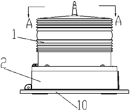
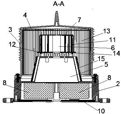
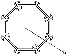
[0028] Such as figure 1 , as shown in 2 and 3, a solar low-intensity aviation obstruction light includes a transparent lampshade 1, a lamp body and a lamp holder 2, the lamp body is arranged on the lamp holder 2, and the transparent lampshade 1 covers the lamp Body, and detachably fixed on the lamp holder 2, characterized in that Fresnel lenses 3 are distributed on the transparent lampshade 1, and a main solar panel 4 is arranged on the inner top surface of the transparent lampshade 1; The lamp body includes a column 6, a luminous body 11 and an installation platform 5. The top of the column 6 is provided with an LED driver circuit board 7, and the bottom of the column 6 is provided with a charging control circuit board 14 and a battery management circuit board 12. The side of the column 6 is equipped with a luminous body 11, the illuminant 11 is located at the focal point of the Fresnel lens 3, the column 6 is connected to the upper plane of the installation platform 5, and t...


PUM


Abstract

The invention discloses a solar low-light-intensity aircraft obstruction beacon. The solar low-light-intensity aircraft obstruction beacon comprises a transparent beacon cover, a beacon body and a beacon base, wherein Fresnel lenses are distributed on the transparent beacon cover; a main solar panel is arranged on the top surface of the transparent beacon cover; the beacon body is positioned in the transparent beacon cover, and comprises a stand column, light emitting bodies and a mounting platform; an LED driving circuit board is arranged at the top of the stand column; a charging control circuit board and a battery management circuit board are arranged at the bottom of the stand column; the light emitting bodies are mounted on the side surface of the stand column, and are positioned in the focal points of the Fresnel lenses; the stand column is connected with the upper plane of the mounting platform; a slave solar panel is mounted on the side surface of the mounting platform; the beacon body is fixed on the beacon base; and two battery sets are arranged in the beacon base. The obstruction beacon further comprises a MCU microprocessor; and the MCU microprocessor is connected with and controls the main solar panel, the slave solar panel, the charging control circuit board, the battery management circuit board, the battery sets, the LED driving circuit board and the light emitting bodies. The solar low-light-intensity aircraft obstruction beacon is high in light source utilization rate and long in service life.

Description

technical field [0001] The invention relates to the technical field of aviation signal lights, in particular to a solar low-intensity aviation obstruction light. Background technique [0002] Low-intensity aviation obstruction lights are usually installed in high-rise buildings, chimneys, iron towers, vehicles in the airport or other moving obstacles to warn aircraft. [0003] Traditional aviation obstruction lights have almost no optical system for LED light sources or only simple optical systems, with large light dissipation and low light utilization efficiency, and light can be seen in unnecessary places above and below, causing light pollution; traditional aviation obstruction lights Incandescent lamps and metal halide lamps are generally used in lamps. These light sources have the disadvantages of low luminous efficiency, high energy consumption, short life, and large lamp body volume and weight. As the fourth generation of new light source, LED light source body adopt...

Claims


Application Information

Patent Timeline
Patent Type & Authority Patents(China)
IPC IPC(8): F21S9/03F21V5/04F21V23/00F21W111/04F21Y115/10
CPCF21S9/037F21V5/045F21V23/003F21W2111/06
Inventor 刘锋
Owner JUNHAN IND SHANGHAI CO LTD
Why Eureka
Try Eureka