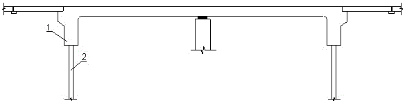
An abutment reaming structure for optimizing the deformation capacity of integral abutment bridges
An integral abutment and abutment technology, which is applied in bridges, bridge parts, bridge construction, etc., can solve the problems of less rigid connections, inability to transmit force, and lack of flexibility, so as to improve the ability to withstand strong external impacts and The performance of the reaction force of the bridge structure, the load-bearing capacity will not decrease, and the effect of the force transmission structure will be improved
- Summary
- Abstract
- Description
- Claims
- Application Information
AI Technical Summary
Problems solved by technology
Method used
Image

Examples
Embodiment 1
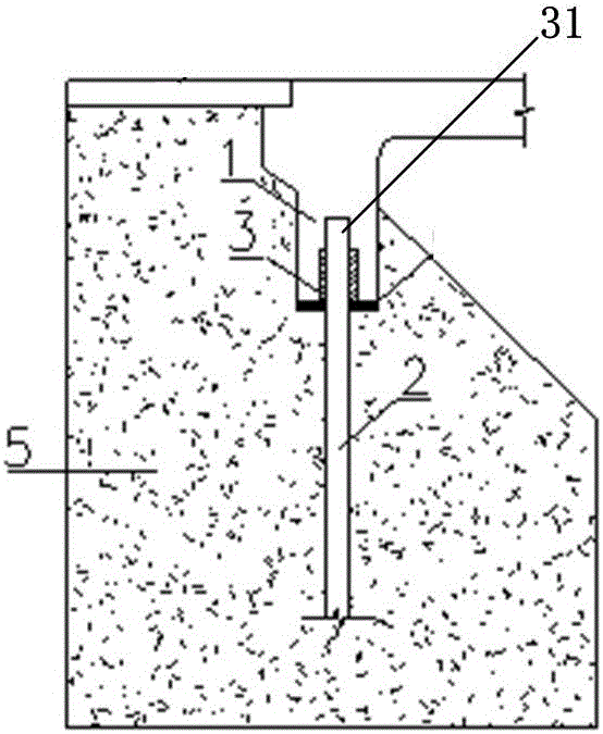
[0032] When the abutment reaming structure adopts such as Figure 4 In the sliding connection shown, in daily use, the bridge deforms slowly in the horizontal direction due to the temperature load, and its deformation pressure acts on the supporting pile 2 through the abutment reaming 30 of the abutment 1, due to the abutment reaming 30 and the support There is a deformation layer 3 between the piles 2. The deformation layer 3 first produces elastic deformation under huge pressure, and distributes the pressure to reduce the horizontal load borne by the supporting pile 2. Because the material of the deformation layer 3 has certain fluidity, the deformation layer 3 Under the huge pressure slowly generated by the temperature deformation of the bridge, the material in the deformation layer 3 in the pressure direction is gradually squeezed aside and redistributed to produce plastic deformation. The deformation layer 3 exerts its elastic and plastic deformation on the bridge. The hori...
Embodiment 2
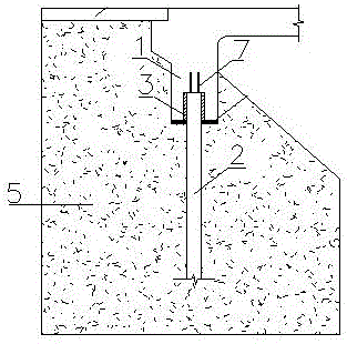
[0034] When the abutment reaming structure adopts such as image 3 The hinge shown, when an earthquake occurs, the bridge will vibrate rapidly and greatly. The vibration will act on the supporting pile 2 through the abutment reaming 30 of the abutment 1, because a deformation layer is provided between the abutment reaming 30 and the supporting pile 2 3. Due to its elastic characteristics, the deformation layer 3 produces reciprocating deformation under huge reciprocating loads and effectively absorbs the load. The material of the deformation layer 3 has certain fluidity, can disperse the impact force generated by huge vibrations, and effectively reduce the reciprocation of the concrete pile foundation. Destroy under load. At this time, the connecting steel bar 7 on the top of the supporting pile 2 is deformed under the torsion force, and the deformation is used to dissolve the reciprocating load caused by the earthquake at the steel bar 7, while still maintaining the supporting p...
PUM
 Abstract
Description
Claims
Application Information
 - R&D
- Intellectual Property
- Life Sciences
- Materials
- Tech Scout
- Unparalleled Data Quality
- Higher Quality Content
- 60% Fewer Hallucinations
Browse by: Latest US Patents, China's latest patents, Technical Efficacy Thesaurus, Application Domain, Technology Topic, Popular Technical Reports.
© 2025 PatSnap. All rights reserved.Legal|Privacy policy|Modern Slavery Act Transparency Statement|Sitemap|About US| Contact US: help@patsnap.com