Railway transportation torpedo car brake device

A technology for a torpedo tank car and a braking device, which is used in transportation and packaging, railway car body parts, pneumatic brakes, etc. Influence, safe and reliable parking brake, high effect of parking safety and reliability

Inactive Publication Date: 2015-08-12
SHANDONG IRON & STEEL CO LTD
View PDF7 Cites 0 Cited by
  • Summary
  • Abstract
  • Description
  • Claims
  • Application Information

AI Technical Summary

Problems solved by technology

[0002] The torpedo tank cars of various specifications in the prior art generally do not have a braking function, because in some usage occasions, the running line of the torpedo tank is limited by the site, and has a relatively large slope, and some have a maximum slope of 5.4‰. It is about 3‰. When the locomotive is running with two heavy torpedo tanks on top, the daily speed of the locomotive will decrease due to the relatively large slope. During transportation, the braking ability of locomotives with only 1 / 10 of their own weight is seriously insufficient. In addition, the traction force of locomotives is small and the slope of the railway line is large. In order to increase the braking device, the biggest difficulty is high-temperature operation. The torpedo tank body is designed as two separate and relatively independent running parts, and the torpedo tank is used as a link in the middle. First of all, it has a great influence on the temperature of the air source from the locomotive for air braking. Secondly, the tank body must rotate 360 ​​degrees during operation. The above two reasons are the main reasons that restrict the installation of air brake devices on torpedo tank cars.

Method used


Image

  • Railway transportation torpedo car brake device

Examples


Embodiment Construction

[0018] In order to better understand the present invention, the implementation manner of the present invention will be explained in detail below in conjunction with the accompanying drawings.

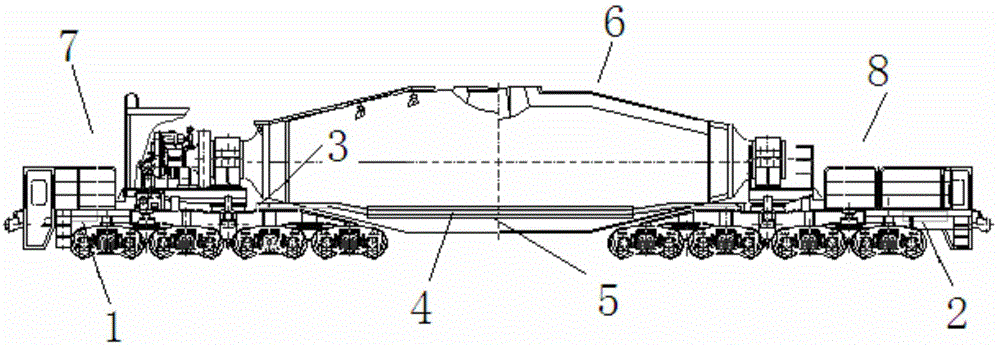
[0019] Such as figure 1 As shown, a brake device for a torpedo tank car includes a left brake unit 1, a right brake unit 2, and a brake main air duct 3. In the space near the right side of the bottom, the left brake unit 1 is arranged in the space of the underframe 7 of the running part of the left end of the torpedo tank body near the bottom of the left side of the middle beam, and the right brake unit 2 is arranged in the space of the bottom of the torpedo tank body. The underframe 8 of the running part at the right end of the tank car body is in the space near the bottom of both sides of the middle beam on the right side, which solves the influence of the high temperature of the tank body on the wind source, and designs the air brake unit into two parts, which are respectively instal...


PUM


Abstract

The invention discloses a railway transportation torpedo car brake device. The railway transportation torpedo car brake device comprises a left brake unit, a right brake unit and a brake main air pipe, wherein the brake main air pipe is arranged inside the space, close to the right side, of the bottom of a left end walking portion car underframe of a torpedo car body; the left brake unit is arranged inside the space of the bottom of the two sides of a middle beam, close to the left side, of the left end walking portion car underframe of the torpedo car body; the right brake unit is arranged inside the space of the bottom of the two sides of a middle beam, close to the right side, of a right end walking portion car underframe of the torpedo car body; the brake main air pipe is connected with a locomotive brake air cylinder through a pipeline and connected with a unit brake cylinder of the left brake unit and the left end of a brake movable hose; the right end of the brake movable house is connected with a unit brake cylinder of the right brake unit, and then a closed ventilation pipeline is formed. The railway transportation torpedo car brake device is especially suitable for torpedo cars operating on the occasions with large gradients and needing brake and parking, parking brake is safe and reliable, and influences of high temperature operations on the brake device are reduced.

Description

technical field [0001] The invention relates to the technical field of railway transportation equipment, in particular to a braking device for railway transportation torpedo tank cars. Background technique [0002] The torpedo tank cars of various specifications in the prior art generally do not have a braking function, because in some usage occasions, the running line of the torpedo tank is limited by the site, and has a relatively large slope, and some have a maximum slope of 5.4‰. It is about 3‰. When the locomotive is running with two heavy torpedo tanks on top, the daily speed of the locomotive will decrease due to the relatively large slope. During transportation, the braking ability of locomotives with only 1 / 10 of their own weight is seriously insufficient. In addition, the traction force of locomotives is small and the slope of the railway line is large. In order to increase the braking device, the biggest difficulty is high-temperature operation. The torpedo tank ...

Claims


Application Information

Patent Timeline
Patent Type & Authority Applications(China)
IPC IPC(8): B61H11/06
CPCB61H11/06
Inventor 周瑞宋艳丽李大军刘淑洁张文刘成军
Owner SHANDONG IRON & STEEL CO LTD
Why Eureka
Try Eureka